Category: Uncategorized

  • Bionicle Display Project Part 8 – Screwed

    Week 8 now, not counting spring break. This puts us at halfway through the semester. I feel like time has really slowed down now.

    Updates

    While I usually don’t talk about my personal life in these since it isn’t relevant to the project, I have a few things to bring up from spring break.

    First of all, if anyone out there is looking to upgrade or build a new computer, I recommend not buying Nvidia GPU’s unless you have a really good deal on the high-end cards. Nvidia cards have been becoming increasingly overpriced compared to their competition, and their design choices baffle me. I had the cable for the 3090ti break on me because it’s been getting squished in every computer case I’ve had because the 3090ti is already so wide, and the cable just barely fits. And now AMD is producing the 9700xt which has amazing value for its performance.

    Amazon also failed to deliver the replacement cable to my address, causing me to hunt it down the entire weekend despite getting overnight shipping, because the replacement wouldn’t arrive until today. Because my computer was out of commission, I ended up playing more of Armored Core 4 on the PlayStation 3, which has been really fun (after I got good at the game).

    But besides that, there is one other package that arrived over the break that I have been beyond excited to talk about:

    Bionicle tube display featuring Jaller standing in front of cardstock paper with the Inika logo printed on. At his feet is a cardstock display with a picture of his canister, name, and set number. Jaller's head and right hand have fallen off their joints. The display case itself has an angular design with a black bottom and lid. There is a red button on the lid.

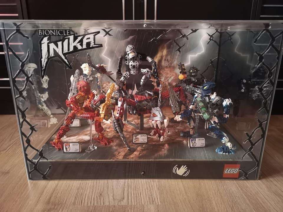
    I managed to get my hands on the only Jaller store display I was able to find on the internet. It took some negotiating, some DoorDashing, and a bit of lucky patience, but it is finally in my hands at long last. This means I can now finally figure out how Lego wired up these swords.

    The display, despite being in a bit of a broken state, poor Jaller, still lights up even brighter than some of my swords with new batteries in them. Despite my initial assumptions, it uses the same flashing feature as on a normal sword rather than a slow fade in and out, which already tells me that they still use the circuit board in the sword, so I worry that it will just be another case of soldering on to the custom board.

    Nevertheless, let’s crack this open and find out for sure.

    In The Flesh

    Full disclosure, I had already opened this up just beforehand just to make sure I knew how, so the screws are easy to remove now, but they previously required some force.

    Taking off the lid, the underside reveals that the button is connected to cables that plug into a cable connector, absolute shocker.

    Underside of the display case's top lid, showing the red button connected to a black and red cable that are bundled up, and plugged into a cable connector

    Beyond that, the cable that this connector plugs into runs behind the paper background, but I’m uncertain how to remove it currently (which I will have to figure out to be able to repair Jaller’s head).

    Something I’d like to point out is the sheer amount of glue that is on this display. Every single joint, pin, pin hole, axle, axle hole, and even each Zamor sphere are absolutely encased in this stuff, almost to a comedic degree.

    As Cartland said, “They really didn’t want this going anywhere!”, which definitely checks out. Between the PET-G plastic casing, the glue everywhere, and the security ties around Jaller’s waist and neck, I have to imagine it wouldn’t even budge even if a kid threw it on the ground and jumped on it like a trampoline.

    At least in 2006 anyway. It seems that joints are commonly broken on these displays today, from everything I have seen online. No matter though, this display is safe in my hands now and I will do my best to treat it with the respect it deserves.

    I already went through the process of purchasing some replacement parts for both the currently broken joints, and for any other joints that may break during this process. But before tearing any of it off, I would like to find out what type of glue is used on these so that I can find something similar for the replacement.

    The glue is oddly springy, transparent, rubbery, and it looks like it flowed very well with how precise some of it fits over these parts. Still though, everyone I have asked so far hasn’t had any clue what it could be. I have a feeling Michael will know though.

    Continuing the dismantling process to reach the sword, I took off the bottom cap thinking that it would let me take the plastic barrier around Jaller, but unfortunately, I was wrong.

    The display case with its bottom cap removed. Jaller and the transparent plastic casing are still connected together.

    Jaller, the background, and the plastic are all connected together somehow. I’m still mostly uncertain how, so I continued to take apart what I could.

    There are a few things on the back side worth mentioning. First is the clamp that was used to attach the display to store shelves, which is screwed in with a massive flathead screw. Furthermore, there is also two small Philips screws, and what seems to be the security band around Jaller’s waist wrapped around two bolts screwed on by nuts.

    Back of the display case, showing a large plastic clamp, along with two screws, and two bolts, all fixed to a black plastic strip.

    I decided to remove the smaller screws first, which, besides making me realize how sharp they were (and putting a few tiny holes in my skin), did a lot of nothing, so I opted to remove the nuts next.

    I untied the security cable, which made me a little uncomfortable, but not too worried since it’s the same type of cable used for bread bags. From there, it was as simple as unscrewing the nuts with a wrench. Unfortunately, this also led to nothing.

    So I decided to try removing the clamp, thinking that it was hiding some other screws behind it. I was able to take off the bottom part just by turning the screw on the bottom, which loosened a nut that was hidden on the top part.

    Back side of the display case, with the bottom half of the plastic clamp removed

    Doing this… also revealed nothing new. I wasn’t really sure where to go from here, so I just tried prying off what I could.

    The transparent white piece, that the initial two nuts kept in place, moved a bit but didn’t come off. Although, it does look like it is a separate tube and cap piece, so maybe with some more force it may be persuaded to come apart.

    Before trying that though, I tried to see if the entire black strip would budge at all. While it did move in the corners, it does seem the piece is glued on, which makes me hesitant to remove without knowing how I’ll be able to put it back together. I’ll see what Michael has to say regarding this.

    It looked like my only option was to try taking off the white block from earlier, so I got to work. By twisting and turning while gently holding Jaller and pulling it, it did come out, but not in the way I was hoping.

    Instead of just the cap coming off, the entire tube came out. I’m assuming this is going to make it more difficult to put it back in later.

    But with it out of the way, Jaller is now much looser, but still held down by the wiring. The wiring goes behind the Inika background, to a space between it and the black strip on the back, so I have no way of taking it out without removing the glue.

    Front side of the display case with the bottom cover removed. A transparent tube sits removed on the outside of the casing, with Jaller being looser than before

    Since I won’t have a chance to talk with Michael until tomorrow, and it’ll be even longer until I get the replacement glue, I decided to just try and wrestle Jaller out of the case as best as I can, and open the battery cover from there.

    I removed the cable around his waist and pulled his broken neck socket through the cable around it, but I still couldn’t get him out of the case, until I spotted a rather well hidden cable wrapping the wires around his arm.

    It was a bit of a pain to get untied at first since I couldn’t find the point where it stuck out, but after some prodding with tweezers, I was able to get it untied and pull Jaller out of the case.

    Thankfully, there was no glue on the battery cover screws, so they came out incredibly easily.

    At long last, I’m able to pull it off and finally discover how it was done by Lego, and…

    Back side of Jaller's sword, showing a standard battery pack with wires connected to it

    It’s… nothing special at all?

    The battery pack inside Jaller's sword removed, showing the wires connected to the circuit board

    It’s literally just the normal component that’s in every standard Inika? That’s it?

    I mean, I suppose my guess was correct, but I was really hoping I would be wrong. Learning this discovery has dampened my spirits quite a bit. It’s starting to seem like the best option, or maybe even the only option, will be to solder my cables together. I’ll have to brainstorm incredibly hard to figure out a solution.

    But, with this discovery made, I have no more use in tearing this display apart anymore. I’ll work on fixing up Jaller as a side project and keep the progress chronicled on here, but other than noting what glue is used I’m guessing that’s about all there is to this display. Although it will still serve as a good inspiration of what I want my display to look like.

    While reassembling the case, I first forgot to put the battery cover back on to the sword, and then had a lot of trouble with the two nuts on the back of the case. I discovered that they were actually attached to Philips-head screws behind the paper background, and I wasn’t able to tighten the nuts back on because the screws became loose. So, I unfortunately had to damage the paper a little bit to fit a screwdriver in and allow me to tighten the nuts on.

    Thankfully, the damage is mostly hidden behind Jaller, but I absolutely want to avoid something like this in the future if I can help it.

    Besides that, I didn’t have any trouble putting the transparent rod back in, which was good, and the rest of the case was just as easy to put back together as it was to take apart. I’m still not sure what those two smaller screws on the back were used for; they didn’t affect anything coming out, and they screwed back in without any issues, so I know they weren’t just keeping the paper background flattened, or something.

    As I said before, I’ll work on repairing this as a side project, and it’ll still be useful to have for references, but I’m still a bit devastated that I wasn’t able to find any more clues on how to tackle the wiring.

    Back to the Start

    While I was working with the display case, I tried coming up with solutions to my wiring problem, and I did come up with something. I don’t believe it’s a good something, but it’s better than nothing.

    Every time I’ve dug around the electronic part boxes in the DKC, there’s been one cable that has caught my eye:

    Small, square, black cable connector with some kind of tape around it and its wires

    This oddly short cable connector. I’ve seen some that look similar to it, pictured on either side of the connector below, but I’ve been unable to find any similar connector that is as short as it.

    Two more square cable connectors, noticeably longer than the short cable connector next to them

    I wasn’t really sure how to look it up, so I asked ChatGPT about it.

    The AI told me that it’s most likely a modified version of the cable connectors seen above. This would explain why I can’t find one of these length’s out of the box, and why it also has tape, or perhaps a shrink-wrap, around the cables.

    With this knowledge, I attempted to try making a modification myself. I took two of the single wire connectors (because I couldn’t find any of the 2 pin ones), wrapped them together in electrical tape, and then just tried cutting them in half with cutting pliers. I then wrapped the cut point in more electrical tape, and was left with this:

    A custom cable connector wrapped together with blue electrical tape

    It’s not the best, and the terminals inside the plastic housing are trying to fall out, but it should technically work.

    I tried to fit it into Matoro’s test sword, but unfortunately the design is still too long, and the tape isn’t flexible enough to fit in, but I also can’t remove any more of the housing or tape since the metal terminals will fall out, so this design does not work.

    It seems my best option is to just use one of the basic white 2 pin connectors commonly seen on Amazon, so that’s what I’ll have Cartland buy.

    Doing the same thing over and over…

    While I await the arrival of the cable connectors, I opted to continue refining the prototype I have now.

    I took the only available cable connector here and modified my LED block until it fit properly, giving me this result:

    Black 3D printed LED block with an LED diode connected to a cable connector, with wires running out through a hole in the side of the block

    I also switched out the yellow LED that was previously in it to a blue one to match Matoro’s sword. While it looks similar to when it had the yellow LED, there are two key changes.

    First, I removed a section of the leg splitting bar in the middle. I found that it was incredibly difficult to remove the yellow LED and then insert the blue one because of the bar, plus it also limited the agility of the legs which wasn’t ideal. Going forward, I will incorporate this change into the initial design of the block.

    And second, I removed an extra corner by the wires. This was because while trying to fit it into Matoro’s sword, the cables needed a bit of extra space to be flexible enough to bend the way I needed them to. I won’t be able to apply this change to the base model though, since the side the cables run through will change depending on the position of the Toa’s sword. Whatever way will hide the cables the most is the way I’ll orient them.

    I also plan to add a proper lid to this design as well. While removing the leg splitter allows the legs to move more freely, it also causes the LED to fall out fairly easily. Adding a lid would solve this problem with no hassle. For the lid, all I need is a 1mm thick plate in the shape of the bottom of the block, with some pins to keep it locked in place, just like the original design.

    I printed the design a couple of times and messed around with it, but unfortunately I discovered a few flaws. First, the pins on the LED block itself made the whole thing awkward to print, and no matter which way I did it, the pins never came out round enough to fit into the lid. And the lid itself was too weak, snapping open each time I tried fitting it onto the LED block pins. I also generally struggled to keep the wires contained within the block and sword compartment.

    I’m not sure if increasing the internal density of both the block and lid would help, or if I just need to make the pins bigger, but regardless I wanted to take a break from it while I wait for the rest of the cable connectors to arrive.

    Back to Base-ics

    I wanted to focus again on the base of the display, since I felt a little worried about how little progress I’ve made on it.

    I did some painting on a separate piece of XPS foam again just to get more practice with the actual colors, now that I’m more confident in what I need to do for it.

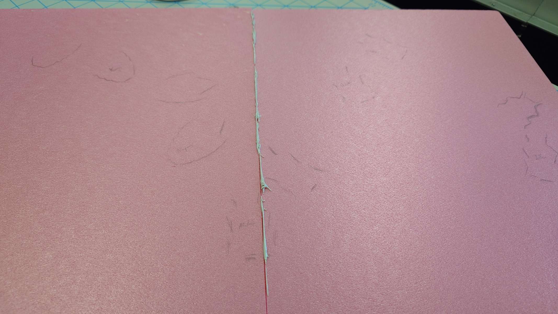
    On the underside of the test piece of XPS foam, I coated it in a mixture of Mod Podge and black acrylic paint, painting two layers on it, to act as a primer. It dried super quickly, giving a pretty satisfying result.

    A board of XPS foam covered with black primer paint

    There are a few bumps along the surface that I want to avoid when creating the final product, but I’m not entirely sure what’s causing them. My current guess is that it’s just the brush that I’m using. I’ll probably try cleaning it out as thoroughly as I can and hope it helps.

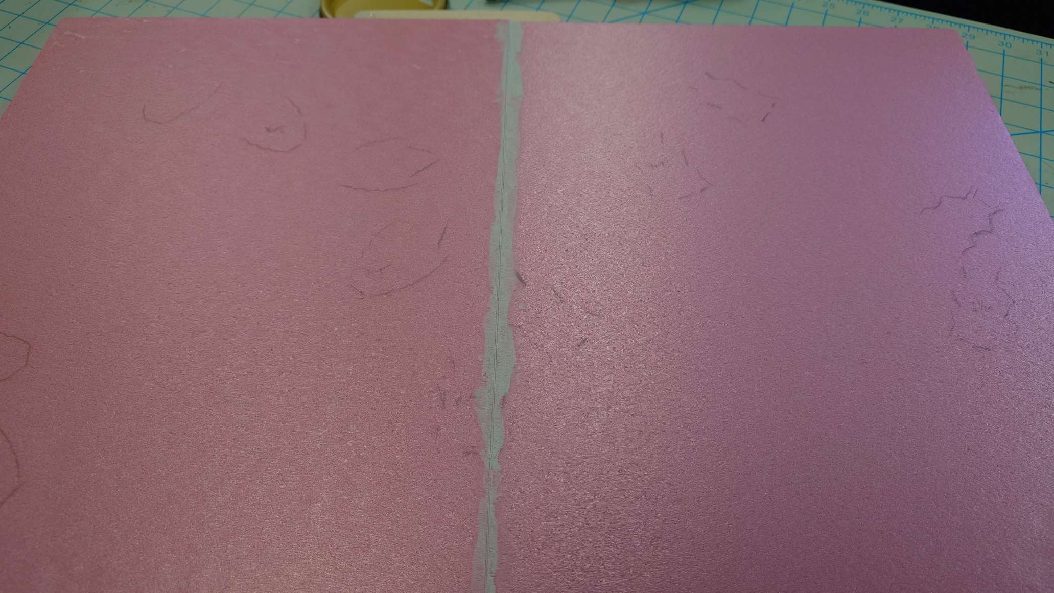
    But, continuing onward, I painted a layer of gray over the primer mixture. While the idea I have in mind is to have a metal-like floor, and the gray I’m using is matte, I’m assuming adding a semi-glossy paint varnish will help achieve the look. If not, then I’ll have to order specifically a silver color paint.

    While waiting for this layer to dry, I began printing the bolt and nut idea I had from awhile back, so that I can hopefully ground the Toa without worry. As much as I’d like to use the same technique from the Jaller display case, it unfortunately won’t work too well in my larger case.

    Results

    The first thing I noticed after it came out was that it’s just a tiny bit small.

    A white 3D printed bolt and a white 3D printed block with a screw hole in the middle. The bolt is covered in sharp edges that ruin its circular shape

    The screw does fit within a pin hole, so that unfortunately means I can’t really make this design much bigger, and because of its size, there’s a lot of imperfections on the bolt so that it won’t screw into the block without a lot more effort.

    As I was fiddling around with it though, I suddenly realized I’m just trying to do the exact same thing as seen on Jaller’s display, just with a different looking nut. So, I went digging for some nuts and bolts.

    I also grabbed some basic screws just to see how they would work, and tried them first with Matoro.

    Matoro hanging upside down from a piece of XPS foam, displaying that the screws work well

    Which worked surprisingly well. I’m still a little worried about the long-term stability of this solution, but I’m thinking that I can place a block of wood, or something of similar material, underneath the foam for the nails to dig into. I’ll only do that if I feel like I really need to though, as getting nails of appropriate length, along with specific sizes of some material to screw into will be annoying to deal with.

    But regardless, I did the same with Nuparu just to try the method with his feet. While the pins in his feet are a bit more troublesome to access, the technique works just as well.

    Nuparu screwed into the XPS foam, standing next to Matoro

    This now means we have a solution for both the anchoring problem and the wiring problem. The only thing left to do is practice hiding the wiring around the Toa and running it through the foam to connect to the Arduino board. One I’m confident in doing so, I’ll be ready to start putting this thing together.

    And since I can’t move forward without those cable connectors, this will be a good stopping point for the week. I really feel like I’m heading towards a conclusion with this project, even if there’s still so much left to do.

    I’m still incredibly worried about the Plexiglass casing, and I can’t even say “I’ll worry about it when the time comes” because that time is coming up very soon. I imagine I will be dealing with it in no more than three weeks. And beyond that, there’s still the issue of the printed graphics and such, which will come up just as fast as the Plexiglass.

    But there’s nothing I can do about it right now except get some rest and prepare for the upcoming challenge.

  • 03 New Idea ≈ Old Idea

    What I found:

    While looking back on some old projects, I dug up something wonderful. It is a simple idea, creating music from the ratios found among the orbital periods of stellar bodies.

    Each body (planet) has a single note assigned to it, this note is selected from a scale and the organization of the pitches is based in either the mass or diameter of the celestial body.

    It has been at least three years and I have yet to find the notes I took on this idea so I will have to recalculate what the ratios are.

    The rhythm of this musical idea comes from the orbital periods, or how long each planet takes to orbit the sun. I took Mercury as my reference point since it orbits the fastest. One orbit of Mercury’s was then used to find a ratio of all other planets.

    Finally, the note duration was determined by the distance from the sun, this was purely subjective as I thought it gave a nice balance between the persistent ticking of mercury and the rarer and more impactful low tones of Saturn and Jupiter.

    At the time I was making this I thought it would be very cool to have a visual to accompany it, well, here’s the perfect opportunity.

    What I am going to change:

    The initial project was relatively rough, I used a very similar sound for each note which makes it cohesive but I don’t find it particularly compelling. As I take the time to edit the project and work on it further, my main goal will be doing more sound design. I would like to characterize the planets more with their sounds and make something more generally pleasant sounding.

    I also want to spend some time turning this from an endless loop into an arranged piece of music, which conveys a stronger sense of direction.

    What I am going to add:

    As stated above, I would like to visualize this, I think a very direct visual of abstract planets orbiting a sun will work wonderfully. To begin illustrating this idea, I have made a new p5.js sketch that simply shows a rough orbit for each planet. The scale is roughly accurate in that the orbits represent the average distance from the sun for each planet, though, they are perfectly circular and flat. Below is the output of that sketch, that tiny little spec in the middle is the sun (at this resolution the sun isn’t actually visible, the planets themselves will be orders of magnitude smaller) and the largest circle is the orbit of Neptune.

    9 black concentric on a grey field.

    I think I will have to spend some time discovering a good balance between accuracy and legibility, I don’t imagine I’ll keep the sun this small and the planets will be impossible to see at this scale (as they are, in fact, incredibly small next to the sun).

    Below is the code that produced the above image

    const diameterOrbitScale = .075;
      
    function setup() {
    createCanvas(diameterOrbitScale*3000, diameterOrbitScale*3000, WEBGL2);
    noLoop();
    }
      
    function draw() {
    background(225);
      
    stroke(color(0,0,0)); // Black outline
    strokeWeight(1); // Thin outline
    
    // The Sun
    
    push(); // begin drawing group with isolated styling/effects
    fill(color(255, 255, 0)); // yellow
    noStroke(); // No Outline
    circle(width/2, height/2, diameterOrbitScale*1); // Sun
    pop(); // stop drawing group
      
    // Inner Orbits
    
    noFill(); // No fill color
      
    circle(width/2, height/2, diameterOrbitScale*42); // Mercury orbit
    circle(width/2, height/2, diameterOrbitScale*75); // Venus orbit
    circle(width/2, height/2, diameterOrbitScale*110); // Earth orbit
    circle(width/2, height/2, diameterOrbitScale*165); // Mars orbit
    
    // Outer Orbits
    
    circle(width/2, height/2, diameterOrbitScale*560); // Jupiter orbit
    circle(width/2, height/2, diameterOrbitScale*1000); // Saturn orbit
    circle(width/2, height/2, diameterOrbitScale*2000); // Uranus orbit
    circle(width/2, height/2, diameterOrbitScale*3000); // Neptune orbit
    }

  • Baseball Podcasting: Refining the Product – Blog Post #4

    Building out Resources

    I spent a lot of last week working on midterms for classes, so I wound up having to do both weeks worth of tasks over Spring Break. This is not a bad thing, as I enjoy working on this project and I was mostly hanging out at home anyway. The only roadblock I hit with that is that my computer drive is too full to download the new audio file for Episode 1 and my external drive to put things on and clear space is at school in Fredericksburg, while I am at home in Fairfax. I need to be able to download it to put it in Soundtrap to add music and other transitions to the audio, so it seems like that will have to wait until the next round as the last step before publishing this episode.

    I still had plenty to work on though. I built out the website more, linking the StoryMap to one of the pages and starting to make road trip itinerary maps for another page. To link the StoryMap, I could not figure out how to make the title card for that page bring me directly to the StoryMap, even Google was no help there, so I wound up writing a little bit about the StoryMap and its purpose on that page and providing a physical link. That can probably change pretty easily to make it better, but for now it seems like it will work. For the road trip maps, I used google maps to outline a possible trip and linked to each google maps page so if anyone wants to change order, add, or take away for their own use, they have that ability. So far I only have 3 maps. One is for ballparks on the National Register, one is for ballparks on the StoryMap not on the National Register, and one is for baseball related museums. I am going to add more, I am just not sure what would be good yet.

    Screenshot of a Google Maps page showing a route that goes around the Eastern United States
    A screenshot of the map for National Register listed ballparks. This is one possible choice out of a few on the website

    As far as the podcast prep, I have spent a lot of time with supplemental material. I listened to the episode again to find what I needed to elaborate on and wrote some information to go on the website for those things, and I found sources to back it up and cited them. That part was easy, but also the most time consuming. I also found the rest of the sources I need to cite in the transcript once I get to that, so that will make it easier once I get to it. I am storing everything in Zotero, which generates citations on its own. This really helps the process go quicker, and makes it easy for me to go back to different sources. I also listened to some of the stock music in Adobe Podcasts, and while some of it is okay, it is not quite the vibe I am looking for so hopefully Soundtrap will have something better.

    Conference Prep Some More

    Wednesday February 26 was when my paper was due for the Middle Atlantic Archaeological Conference, so I turned that in then. Really it is due when I present on March 21, but I entered a student contest for it, so that is why it was due sooner. Now all I have to worry about is the presentation, and I have all my pictures, I just need to make a PowerPoint and prepare what I am going to say. I went to the Southeastern Archaeological Conference in Williamsburg, VA in November, and a lot of presenters just read their paper like a script. I could do that, but as someone who does a lot of interpretive programs I would rather have an outline for myself and talk more casually about things than read a script. I feel like it makes it more engaging and a better quality conversation overall. I am going to use the paper to make that outline, but it will be more bullet points for the presentation. For the Powerpoint, I am making it really simple with just pictures to back up my talking and show the audience the ballparks, people, and other resources I am talking about. I have a lot to show, and I may have to find some different pictures to go in it, but I have most of what I need already so that should be attainable.

    Next Steps

    When I return to school, I am going to clear the space on my computer to download the audio and finish that, then I am going to fix up the transcript for spelling and punctuation errors and cite everything in that. When that is done I think it will be ready to go up on the site, so hopefully that will be part of the next update. The Conference will also be included though, since that is at the end of the next two weeks, so time might hold me up a little bit, but I figure I can shoot high and be humbled if needed. That is part of the fun, and I learn something regardless so I consider that a good thing. Wish me luck in Gettysburg!

  • Bionicle Display Project Part 7 – Painting a Portrait

    Week 7 now, hopefully it’s a little more organized than last week went.

    Painting Update, again

    Starting off this post, I’m happy to report that the acrylic paint I applied from last week has dried fully and successfully.

    A painted XPS board with new, dried streaks of gray in various spots around it.

    The gray acrylic paint is as dry as the brown oil paint is, in only a fraction of the time.

    Of course, I need to thicken it quite a bit so that the streaks and primer aren’t visible, but this is good knowledge to have.

    Furthermore, I have found that it is best to paint on the mod podge primer instead of just straight black paint or on to the board directly. The primer is effective in keeping the paint stuck on, and it doesn’t rub off on to my finger like the other two applications do.

    I’ll apply some extra layers and see how it turns out, but we finally have a conclusion on this saga in sight.

    Mind the Gap

    Keeping to the theme of the XPS boards, something I failed to do last week was apply hole filler to the gap of the display board, which I will remedy now.

    The seam is a lot smaller than I remember it being, and the hole filler putty I have is meant for much larger holes, but I’ll make it work. I opted to use the tip of a skewer to dip into the putty and fill the crack.

    I had some trouble getting the putty to come off the skewer and stick to the foam, but a little bit of persistence changed that up. I also came to the realization that the putty wasn’t just going to fall into the seam on its own, so I opted to place some “little wormy dealies”, as Adam so lovingly refers to them as, along it, and then smoosh it down with another popsicle stick.

    Left ImageRight Image

    While it and the paint dry and set, I’ll do some more digging into cable connectors.

    Forming a Connection

    After multiple hours of research, chatting with ChatGPT, more research, daydreaming, and finally some experimentation, I discovered that the best option I have, if I don’t want to solder wires together directly, is to readjust my LED block design.

    The problem I was facing is just the lack of space to work with. Without any changes, my only option is to have items be custom made for my needs, which I want to avoid. Thus meaning, I have to make some fundamental changes.

    While throwing ideas at the wall, I ended up forming the idea of turning the LED on its side so its legs are facing to the left or right of the block, when looking from up top. This would then let me fit a basic 2 pin connector in the empty space.

    An LED diode nestled inside a 3D printed housing, connected to a white cable connector with wires feeding out of it.
    A very rough prototype

    To accommodate for the changes made in my prototype, I switched the LED leg separator to be on its side rather than facing upwards, which will give me the freedom to lay the LED on its side, while still being supported from underneath, and hopefully also keeping the legs from crossing over each other.

    I also added a base to one side of the empty compartment so that I can create gaps in the sides of it without compromising the structural integrity of the block.

    I’ll need to make some more tweaks, but a fuller prototype looks as such:

    I opted to use a yellow LED since I was worried about running out of other colors

    I worked to try and fit this contraption into Matoro’s empty sword, but I had some serious design flaws that stopped me. Notably, I had trouble getting the LED to stay connected to the connector while I was fitting it into the sword.

    It frustrated me a great deal, so I opted to take a break from it for a bit. I have something cooking up in the background that will hopefully solve all of my problems here, but I’ll wait until I have tangible results to announce that.

    Based? Based on what?

    To pass the time, I decided to move back to the display base. I originally intended to paint it now, but I realized it would probably be a better idea to figure out how I’m going to keep the Toa positioned on it before that.

    I brainstormed ideas for a bit, and I figured it would be easiest to make use of the pin holes that are on the Toa’s feet already. I came up with the idea of having a custom printed pin with a stopper on top of it that would connect through the foot and into a Lego pin connector that is under, or within, the foam. I also thought of making a web of Technic rods underneath the foam that the Toa would connect into, but I don’t believe it would be very stable.

    I continued on the pin stopper idea and eventually thought of a design that was literally just a normal screw, which gave me the brilliant idea to try drilling a screw in. Attempting this with the small screws from the sword’s battery cover yielded acceptable results… Until I gave the slightest bit of tugging which ripped the screws out, as I expected.

    To remedy this, I thought back to my small experience with theater set creation and home improvement. When you want to hang something up by means of screws in a wall, you either check to make sure you’re drilling into a stud, or you use an anchor.

    I searched up to see if there were any screw anchors I could 3D print, but while browsing through them I suddenly thought of an alternative idea on how to keep the Toa in place.

    Anyone who has bought a Figma or Nendoroid before will be familiar with the idea of having a transparent stand that connects to the figure to keep them from falling over. I thought about trying this idea, but I realized very quickly that it still leaves me with the same problem. How do I stabilize the stand? Screwing it in seems to be the only option.

    So I continued looking for information about anchors.

    That Ship Sailed

    I searched to see if anyone had tried putting anchors in foam before, and I came across one blog post where someone was asking about just that. Unfortunately, most of the responses said that it just isn’t going to work, because foam doesn’t have enough structural integrity to keep even the anchors in place.

    So it was back to brainstorming. Keeping with the screw idea, I came up with using a bolt and nut style design. My idea is to have bolts that run through the pin holes on the Inika’s feet that will then screw into a nut embedded into a plate underneath the foam.

    My thought process for putting the nut into a larger plate is that it’ll add more surface area to prevent the nut from tearing a hole straight through the foam. Furthermore, I’m thinking that I can embed the nut design into a larger plastic plate so that there’s even less of a chance it’ll damage the foam. But before that, we need to try a prototype to make sure the idea works at all.

    I used a free nut and bolt model and made the necessary modifications to each of them in Blender.

    I ran out of time for this week, quite suddenly, might I add. Next week is Spring Break so it’ll actually be two weeks before I return to this project again. I’m looking forward to the refresh.

  • Baseball Podcasting: Teaching a College Class! – Blog Post #3

    Editing the First Episode

    Issues have been resolved! It turns out a combination of needing to clear out space on my computer because the hard drive was full (it would not download the audio and I could not figure out why, gotta love troubleshooting and independent problem solving!) and needing to change the audio file from a .WAV file to a .mp3 file were all I needed to do. I used Sound Trap to do this, just putting the .WAV in and exporting it as a .mp3 and putting that into Adobe Podcasts. It transcribed easily and now I can use that to edit. Huzzah! Now to tolerate listening to myself talk. I am thankful I could edit out all the um’s, uhh’s, like’s, and dead air space without having to listen because that would have been torture, and I cut about 9 minutes off the episode by cleaning all of that out. That is wild, I thought I was a better talker than that. Anyway, progress is being made, so now I can have some fun playing with everything.

    A Screenshot of an editing workspace on Adobe Podcasts and the beginning of a transcription of an audio file
    The Editing Workspace for Episode 1 on Adobe Podcasts. It’s a pretty cool system to use.

    After cutting everything that was just filler space out, I listened to it again to make sure it still flowed smoothly, and I feel pretty good about where it is at. I do have some small issues with enunciation, but that is not something I can fix with editing, I just need to work on that in future episodes, and that will come with practice.

    Creating preservingourpastime.com

    This is progressing too, slowly, but it’s getting there. I installed WordPress on the domain and then had absolutely no clue what I was doing. A DKC consultation appointment came in clutch there. They showed me how to add pages to the site, how embedding things works, and a basic overview of how to put other things on the site. After that I started playing with it, put in pages for the StoryMap, Podcast, and some road trip ideas, and now I need to populate these pages with content. I have some preliminary road trip maps already made for the ballparks I researched, so that will start that page. I will put the podcast up once I finish editing and making the extra content to go with it. Embedding a StoryMap gave me a challenge, so I will have to figure out how to do that too. It seems fun to build out so far, and I’m sure it will be more so once I figure more features out.

    The homepage of a website on WordPress with some preliminary text and not much other design
    The shell of what the website will become, Seems like a good start

    Side Quests for the Project

    During this stretch of the Fellowship, not one but two side quests came up. The first is that I started writing a paper to present my research from the StoryMap at the Middle Atlantic Archaeological Conference in Gettysburg, PA in mid March. That is pretty awesome and not at all stressful, but I have had help from my Archaeology professor to know how to format the paper and what kinds of things I should write about. Now just writing the paper with the research I have already done is pretty straight forward. I have been trying to find ways to emphasize baseball as something to care about while appealing to preservationists who may not care about baseball specifically, so that part had been a fun brain puzzle. I wrote a draft and am now working on refining the paper to make it coherent and captivating. Now that I’ve written something, I’m getting pretty excited for the presentation even though it is not for another month, but that allows me to make sure it is as good as it can be.

    Side Quest number two is that one of my former history professors is teaching an American Studies class this semester called “Baseball in America” and this week is about Historic Ballparks. He asked me to come teach his class for a day (Friday, February 21 if you were wondering), so I agreed because he has taught a couple of my favorite classes in the past and it is a chance to show off what I have done so far with the project. I have been brainstorming that, and preparing ideas for how to best use it as a teaching tool in a classroom environment. Going to the actual class I just had my StoryMap and an outline of basic points, figuring I’d just talk about things and make it more of a discussion. I actually used the part of my Preservation Overview podcast episode outline about integrity as a guide for my discussion, using examples from the StoryMap of how the different aspects of integrity are used in different ballparks, and that seemed really well received by the class. After talking about integrity, I talked about adaptive reuse and how ballparks that are no longer in use can still serve a purpose for their communities. That was an even better discussion and the class had a lot of really good ideas. I am really proud of how well I did, and the professor also had positive things to say, teaching is cool, and I hope I get to do it more. I guess in a way that is what I am doing with the podcast, so that is a big added bonus.

    Next Steps

    For editing the Podcast, now that I have gotten all of the clunky audio jibber jabber out, I can start adding transition sound effects and other things to make it a polished episode. That should not take too long, and once that is done the audio file itself will be ready. I am going to use SoundTrap for that, since it is a little more intuitive for what I know already.

    For the supplemental content, I need to put the final file into word to transcribe again, then edit it to make sure things are spelled right with good punctuation, then I need to cite my sources. I also need to write a little more context for some of the things I talked about to make it make more sense for the webpage for the episode, so all of that will take a little more time.

    For the website, I need to put the StoryMap and Road Trips into those pages, and maybe write some stuff and add pictures for the homepage too so that it actually looks appealing for people that might want to use the site.

    This seems like a lot, but it is manageable and I think will make it look and sound a lot better. That’s all for this update, baseball is fun.

  • Bionicle Display Project Part 6 – Eureka

    Kicking off week 6, I did not manage to get acrylic paint over the weekend, so I will have Cartland order some off Amazon, where it will hopefully arrive quickly.

    I don’t have anything witty to say while writing this, so let’s just get right into business.

    Solving the Enigma

    Because there is still some time before I can print on the 3D printer today, and because I can’t paint the base like I intended, I decided to look into the cabling process again, since I will need to figure out how to run these cables to the LED lights soon.

    I just decided to look at the official Toa Jaller tube display, to get some ideas.

    I initially was having trouble finding some pictures of it that showed more than the front-side view, but eventually I ran into this amazing video on YouTube that goes into a lot more detail for the tube:

    At around the 3:46 timestamp, the reviewer provides this perfect, fantastic shot which shows off the wiring:

    A still frame of a YouTube video. Jaller's golden sword is shown at an angle facing away from the camera, revealing small black and red wires running through tiny holes in the bottom of the sword.

    From the frame, we can see that Lego made some small holes at the base of the sword, just large enough to run some wiring through. This process proves to me that I won’t really have another option other than to make holes of my own on my swords, so I will need to find the proper tool to do so.

    Furthermore, I also reached out to the Instagram account bionicle_sealed_history to ask if he had any more information on these displays. While he didn’t know specifically how the cables were run through the sword, he did inform me of some very important details.

    For one, I was made aware of a larger Inika display that shows off Jaller, Matoro, Nuparu, Hahli, and the Piraka Vezon and his cursed Fenrakk. While I knew that there were other Inika displays like this, this one specifically had a light up function for the Toa which I did not see in any other Inika displays (it was also seemingly triggered by motion!).

    Fun fact – Vezon and Fenrakk

    Story spoilers for Bionicle 2006 in this fact! I’ve tried to keep spoilers light for any of those who are interested in tackling Bionicle’s story in chronological order, but this will be an exception because I have the urge to write one of these facts.

    Vezon (pronounced “vey-zon” and not “vee-zon”) was the secret seventh Piraka, created after Hakann used the Spear of Fusion on Vezok (also pronounced “vey-zok”), causing him to split into two. Vezon was (somehow) more insane than Vezok, and would eventually betray the Piraka to try and beat them to finding the Mask of Life on Voya Nui.

    While the Piraka, and subsequently the Toa Inika (and most likely also Toa Jovan’s team), had to face multiple trial chambers on the path to reach the Mask of Life, Vezon was allowed to freely pass all of them and take the Mask of Life.

    However, the Mask had tricked him into becoming a guardian for itself. Instead of granting its powers to Vezon, like it would with a being who was destined to wear it, it fused itself to his head and became chained to an enlarged Fenrakk spider, cursed to be a guardian of the mask and never leave the Chamber of Life.

    A large Lego display case featuring the Toa Inika Jaller, Hahli, Matoro, and Nuparu, along with the large Bionicle set "Vezon and Fenrakk". There is an icon towards the bottom right of the display that indicates a hand wave. The top left of the display has both the Bionicle and Inika logos. The corners of the display have a flat image of a broken chain-link fence

    On top of this, I was told the following regarding both the larger display and the Jaller tube:

    “The cable was routed along the arm to the back of the Toa. In the case of the small display, the cables were routed underneath the background paper. For the large display, the cables were routed through the Toa’s leg and under the base.”

    While I’m unable to spot the cables in the image due to Instagram’s horrible compression methods (which is probably a good sign?), I at least have a good enough of an idea to figure out how to set up the cables for myself; the specifics of which I will figure out once I reach that step.

    But first, I need a drill, and a very, very tiny drill bit.

    A slight aside

    Further regarding the display case shown above, it also provides a good example of what I’m wanting my final product to look like. Notably, I’ll be reusing the paper background and the small set information displays at the base of each Toa (and Vezon).

    I plan to have the chain-link fence around the edges of the display by using armature wire, as previously mentioned in another blog post, and I plan to have a strip of paper running around the bottom. In the case of this display, this strip only has the Lego logo and a hand motion icon, but I have some ideas to make mine stick out a lot more.

    I also particularly like the addition of the Inika logo on the top left, so maybe I’ll consider adding it on to my display. I’ll see how I’m feeling.

    Checking up on a friend

    I still have some time before I’m able to use the 3D printer, so I decided to check in on the XPS boards I had glued together a couple of weeks ago, because I just realized that I hadn’t done that.

    Two XPS boards glued together. There is a small gap between the boards

    They seem to have set well enough. They feel sturdy, but I wouldn’t be comfortable with applying a ton of force to them. The seam in the middle is bothering me quite a bit though, but I can figure out how to seal it up.

    I went back to check North of the Border for some references, because I remember that he has a certain way of creating mud for his displays, and I planned to use whatever mixture he uses to fill in this seam.

    Luckily for me, he just recently created a creative display featuring the popular Moo Deng (my beloved) and another pygmy hippo battling it out on an outdoor terrain.

    While creating the base for Moo Deng, instead of using his typical combination of Mod Podge and some other items, he just used hole filler to create the mud. It’s so simple, it’s genius. So I now will buy myself some hole filler to seal the gap between my boards (and also to just have on hand).

    Also, while I was scrolling through the video to see the mud process, I spotted Adam using the exact kind of drill I was thinking of using for the Inika swords. I suppose I had just forgotten I got that from him. I checked the description to see if he linked the exact drill he used, but no luck. I assume it doesn’t really matter which one I use though.

    Fun fact! – Moo Deng’s name

    Moo Deng is a pygmy hippo in Thailand, and as such her name is of Thai origin, with “deng” meaning “(to) bounce or spring”, and “moo” just meaning pork. So Moo Deng quite literally means “bouncy pork”!

    Looking Out for the Little Guy

    At long last I have the 3D printer available. I immediately put my sliced LED block model to print. Thankfully because it’s so small, it doesn’t take very long at all, even at the highest quality. This will be crucial for making the most of my time.

    After a short time, I got this result:

    Not bad for a first draft, but it definitely can be improved upon. The studs on my block are a little bit taller than the original, and seem to be just barely thinner in diameter. The LED slot is also too thin to fit an LED in without some damage. As for how it fits in the sword…

    As they say: “Like a glove”. This surprised even me, as I fully expected to have more than a few measurements off by just enough to make a difference, but even the clips I designed are doing very well at their job.

    There’s even enough extra room for a circuit board between the block and battery cover!

    It isn’t perfect however. Like I said, I’ll need to readjust the tube where the LED will slot in, because even putting some force on the LED doesn’t make it slot in very well, and it also expands the plastic, meaning the block won’t fit in the sword as is.

    I’m also thinking about making the battery compartment on the block hollow. Right now I just have it filled in completely solid, but hollowing it out will both reduce the print time even further, and also allow me to fit the cables in.

    I applied these adjustments to the model in Blender to get this:

    Underside of a 3D model depicting the LED block. It has a hollowed-out casing and extra space for an LED diode.

    For the sake of documenting my changes, I hollowed out the battery casing but left a divider so cables would not touch, added a slight curve to the inside of the LED tube by using an elongated sphere to hopefully fit the LED better, and I also added a slight bevel to some edges for decoration and for (hopefully) an easier time putting the LED in the block.

    These changes only removed a minute of printing time (down from 11), which is less than I hoped, but it’ll probably make a bigger difference with higher qualities.

    But, after a few micro adjustments, and a little bit of a printer hiccup, I came out with this:

    Underside of a 3D printed model, showcasing the same design as the 3D model

    There’s a tiny bit of wiggle room for the LED, but it’s not noticeable enough to where I can confidently make another adjustment to the sizing, so this is fine enough.

    But with that, we can now work on a functioning prototype block.

    A Conundrum

    I originally thought of using a cut to size perfboard to solder the LED and cables on to, but unfortunately, I discovered that perfboards are about twice as thick as the original circuit board in the sword.

    It’s not really possible to cut them in half, or sand them that much, and I can’t afford to change the dimensions on my LED block to accommodate them, so I will have to reconsider my approach.

    I tried to find a 1mm thick board online, but they are nearly impossible to obtain. It’s not going to be viable to have a company custom cut them, due to costs and time restrictions.

    My next idea was to use connectors of some kind. The thought is that I would plug the LED “legs” into one side, and then have the power wires on the other, with the connector sat in the hollowed area of the block (which would require a redesign). Ideally, this would make it so the LED is secure and also so that it doesn’t have a chance of crossing wires and shorting out, while also making it more replaceable than if I were to solder the LED legs and wire together directly.

    I dug around some of the electronic parts bins around the DKC for some ideas. Nothing really clicked for me until I found this beautiful cable:

    A cable consisting of three different colored wires, connected on either end by a square cable connector

    I’m not entirely sure what it was, but something about this cable spoke to me. I had my doubts that it would just work or that it would hold the LED properly, but sure enough…

    A blue LED lit up and connected to the cable connector, which is subsequently connected to the Arduino board

    It works beautifully. I don’t think I’ve been so glad to be proven wrong.

    Following off this success, I had a “eureka” moment while fiddling with the LED block. I removed the divider meant to keep the cables separate, and also created holes so that the legs could stick straight down without curving around anything, which led to this:

    A blue LED connected to the cable connector, fit inside the 3D printed block

    I think this is the way to go. It has everything I want, while also having the benefit of not needing to deal with solder. The only issue with this set up currently is that the cable is too large to fit in the sword.

    Two cables with much smaller cable connectors

    Either of these two types of connectors would be my ideal option, since they only have two pin slots and are a lot smaller, meaning I can fit them in the swords much easier.

    I’ll take a look online and see what I can find in terms of these.

    Another Distraction

    While brainstorming some ideas on how I could get this LED to fit, I ended up playing around with the Arduino coding and made a script to flash the LED in the same exact way as the original circuit boards.

    I haven’t mentioned this up to this point, partially because I couldn’t be bothered to record it, but the Inika swords have a specific way of flashing for the extra cool factor, rather than just turning on or turning off.

    Below is a video of Hahli’s sword performing this flashing (left), and my custom Arduino program controlling Matoro’s sword (right):

    A gif showcasing the flashing lights of an original Inika sword, along side a custom programmed light

    My camera’s framerate was a little low for this, but I can confirm that the lights flash in almost the exact same frequency.

    I think this could be a fun addition to add to the final display. The normal state of the lights would be on or off, but I could have an additional, physical, button to cause this flashing. To see all six of the Toa with their swords flashing like this has always been somewhat of a dream of mine anyway.

    Adding this as a separate function will require me to learn how to use inputs on the Arduino, but I am very confident it will be of no issue.

    A Final Quick Update

    The paints and tools I needed arrived on Friday, and despite having enough progress for this week to be satisfied, I decided to at least try on the new paints.

    I applied some layers of grey paint on various parts of my test block of XPS foam, making sure that I would be able to see where the paint looked best. I put a layer on the Mod Podge primer, the straight black oil paint primer, and on the foam directly itself.

    The oil paint I had applied earlier finally seemed to be dry, but hopefully this new acrylic paint will be fully dry after the weekend so I won’t need to wait weeks before being able to use the foam.

    As for my other plans next week… I imagine it will take some time for the cable connectors I pick out to arrive, so in the mean time I’ll start planning how to attach the Toa to the foam board, and how I will hide all of the wiring on the display. I’d like to also start taking a look at how I’ll encase the display, and finally tackle the issue of the Plexiglass problem.

    Should I become overwhelmed with that, my backup plan is to start planning out a design for all of the cosmetics I plan to print onto paper, and do research into the paper I’ll need. From my previous findings, this is going to be by far the most expensive part of the project just due to the sheer cost to size ratio of paper.

    In the mean time, I’ll take a well earned rest.

  • 02 Noodles and Doodles

    I have been doing two things: Re-familiarizing myself with p5.js by duplicating and editing sketches from The Nature of Code, and, following my curiosities with musical systems.

    First, the code. The first parts of The Nature of Code describe making a random walk, this is a simple system where you have a walker, in this case a dot, and every time interval, it takes a step in a random cardinal direction. Up, Down, Left, or Right. It is quite easy and has a pleasantly organic look already. Below is a video demonstrating the walk, and a code snippet of how it is driven.

    // The Nature of Code
    // Daniel Shiffman
    // http://natureofcode.com
    
    let walker;
    
    function setup() {               // once at the beginning of the program, perform this code
      createCanvas(640, 240); // create a window of width 640 and height 240 pixels
      walker = new Walker();     // create a new walker object
      background(255);             // set the background to white
    }
    
    function draw() {       // every frame, perform this code
      walker.step();          // make the walker take a step in a random direction
      walker.show();         // draw the walker in it's new position
    }
    
    class Walker {                      // all the code defining the walker object is in here
      constructor() {                   // run this code when the walker is created               
        this.x = width / 2;             // position the walker in the dead center of the screen
        this.y = height / 2;
      }
    
      show() {                     // run this code when the command walker.show() is run
        stroke(0);                 // set the stroke color to black
        point(this.x, this.y);  // draw a stroke at the x & y positions stored in the walker
      }
    
      step() {                                                  // run this code every time walker.step() is run
        const choice = floor(random(4));        // generate a random number between 0 and 4, exclusive
        if (choice == 0) {                                  // change the x or y position dependent on the random value
          this.x++;
        } else if (choice == 1) {
          this.x--;
        } else if (choice == 2) {
          this.y++;
        } else {
          this.y--;
        }
      }
    }
    

    This code comes directly from The Nature of Code book. All lines, besides the attribution, starting with “//” are comments written by myself to explain the code.

    I decided to run with what was given to me here. After maybe an hour of tweaking settings and experimenting with the background opacity, I found a way to have a random walk that left me with a very organic and flowing movement, shown below.

    You will notice many comments in my own code, this is because while testing new ideas, it can be helpful to retain old ideas. So rather than deleting lines, I comment them out. They do not affect the output of the program.

    let walkers = [];
    
    function setup() {
        createCanvas(800, 800);
        for (let i = 0; i < 2000; i++) {
            let walker = new Walker(17)
            walkers.push(walker);
        }
        background(225);
    }
    
    function draw() {
        background(255, 10);
        for (i = 0; i < walkers.length; i++){
            walkers[i].step();
            walkers[i].show();
        }
    }
    
    class Walker {
        constructor(size) {
            // this.x = random(width);
            // this.y = random(height);
            this.x = width/2;
            this.y = height/2;
            this.size = size;
            // this.hue = floor(random(50));
            // this.shade = color(this.hue);
            this.hueshifts = [50, 20, 50];
            this.shade = color(this.hueshifts[0],this.hueshifts[1],this.hueshifts[2]);
        }
    
        show() {
            stroke(this.shade);
            strokeWeight(this.size);
            point(this.x, this.y);
        }
        
        step() {
            let xstep = random(-this.size, this.size);
            let ystep = random(-this.size, this.size);
            this.x += xstep/7;
            this.y += ystep/7;
            //let stepMult = random(min(width, height) / 200);
            //this.x += xstep*stepMult;
            //this.y += ystep*stepMult;
            
            /* keep walker on canvas horizontally */
            if (this.x >= width + (1.5*this.size) | this.x <= 0 - (1.5*this.size)) {
                this.x = width/2;
                this.y = height/2;
                // this.x = random(width);
                // this.y = random(height);
                // this.size-=1;
                // this.grey -= 102;
                // this.shade = color(this.grey);
            }
            
            /* keep walker on canvas vertically */
            if (this.y >= height + (1.5*this.size)| this.y <= 0 - (1.5*this.size)){
                this.x = width/2;
                this.y = height/2;
                // this.x = random(width);
                // this.y = random(height);
                // this.size-=1;
                // this.grey -= 102;
                // this.shade = color(this.grey);
            }
            
            // const choice = floor(random(4));
            
            // switch(choice) {
            //   case 0:
            //     this.x+=this.size;
            //     break;
            //   case 1:
            //     this.x-=this.size;
            //     break;
            //   case 2:
            //     this.y+=this.size;
            //     break;
            //   case 3:
            //     this.y-=this.size;
            // }
        }
    }


    This code is more convoluted, essentially, I am creating not just one walker, but 2000, they are a larger size, and move diagonally as well. When a walker reaches the edge of the window, they are relocated inside the window. Before reaching this result I experimented with changing the size of walkers that reached the edge or changing their color but none of these were as satisfying of effects to me.

    The final bit of code experimentation from the last couple weeks here was messing with a different type of randomness. Normal (pseudo) randomness, as seen above, distributes random values equally between the minimum and maximum range. Below is an example of a Gaussian noise, this code plots dots on the canvas based on random Gaussian values, that is, there is a concentration around the mean (average) and a standard deviation defines how the distribution changes away from the mean.

    Next up for my coding will be going through more Nature of Code exercises and pursuing my curiosities off of the code given. I am particularly excited and interested to begin playing with random noise, specifically Perlin or OpenSimplex noise, these are techniques for generating random values that create organic shapes because the changes between values are smooth and they lend themselves to animation.


    Next I would like to briefly explain the music I have been experimenting with. Below are two videos demonstrating an asynchronous looping technique. This means I have created at least two loops, repeating sections of audio, that are not the same length, therefore, they do not play in sync. This shifting relationship between the multiple loops is very intriguing to me.

    In this first experiment I have created 7 instances of a virtual flute instrument. Each instance is assigned a note, and a loop length. After each loop, the octave of the note changes to a different one within a set of 3 defined octaves. On the first go-round, we hear all of the instruments playing together in perfect sync, they start together and all of the notes are the same length. The second time we hear the collective chord, the notes are not in line with each other. Each time these individual instruments loop, they fall further apart from each other creating an increasingly complex and interesting relationship.

    In this second experiment, I did something similar to the first. In this case, I have just two instances of an identical instrument, this time a sampled piano. Each piano plays to one side of the stereo field and plays an short identical melody. The only difference is a small shift in the length of the loop and a couple of tiny tweaked settings in one of the pianos to make the timbre so slightly different.

    I found this to be far more interesting to me, having melodies play against each other is far more engaging than simply the long droning notes of the previous experiment. An interesting side effect of how I set up this system is that it does repeat. While the first experiment (I’ve been calling it Flute Loops), is random and will not repeat for an inconceivably long time, this piece (I’ve been calling it Lekko Loops (the piano is named Lekko)), repeats after exactly 6 minutes, the length of the melody loops are a round division of the tempo and relatively quickly are back in line.

    Both of these examples are relatively simple and quickly become uninteresting. As I delve further into this technique and find more textures or arrangements I enjoy, I will leave less up to chance and begin crafting a piece of music that slowly shifts over time, beyond the shifting of the loops.

  • Bionicle Display Project Part 5 – Lights, Paint, and Confusion

    Return

    Week 5 now. I feel like this semester is flying by pretty quickly.

    After sleeping on it for the weekend, I have come back to realize I still don’t want to deal with the LEDs and cables right now.

    A Splash of Color

    Instead, I’ve decided to finally get on with painting the XPS foam. Shortly after I published my blog last Friday, my friend provided me with some paints to borrow. I took some time to mess around with them on a test piece of XPS foam.

    XPS board with spots of black painted on. The bottom right corner has a splotch of brown paint.

    On the bottom right is a primer made from mixing black and some Mod Podge, painted with a mix of brown and white on top. On the top left is black painted straight onto the foam, which did not work very well at all.

    Despite leaving the primer to dry overnight before painting the brown on top of it, which was left to dry over the weekend, the brown paint still feels wet and comes off just by pressing my finger to it. This is the most experience I’ve gotten painting like this, so I’m not really sure what the issue is or how to solve it.

    I followed this Reddit post which, while it doesn’t apply to my situation exactly, does give some seemingly good ideas on what I can do to improve my situation.

    One user states that Mod Podge is supposed to “dry clear”, and to apply a layer of it before applying a separate primer. However, another user in this Reddit thread states that black paint with Mod Podge is a good sealant and primer.

    The common theme between the posts is mentions of keeping the primer layer thin, so I believe my idea was correct, but my process needs to be improved.

    So I brought out the Mod Podge and paint and tried again. I applied some Podge with a wooden stick, threw some black paint on to it, and kept mixing and adding Podge to try and get a dark grey color.

    I tried spreading the layer as thin as I could, but I definitely used WAY too much black paint. Even in person, the color is still just straight black, not dark gray. I didn’t want to keep adding more Modge Podge because I was worried I wouldn’t be able to keep the layer thin, and because it would cover the whole board.

    I’m almost certain that this won’t work, and I’ll need to adjust my mixture of Podge and paint, but we can only wait to see.

    In the meantime…

    Solving the LED Conundrum

    One of the last things I had talked about in my last post was how I could store the LED lights in the swords so that they could be replaced but also would stay in place securely.

    I talked to Shannon and Cartland about my ideas and we came to the conclusion that it’s worth at least trying to design a casing for the LED before tearing the original casing apart.

    I tried looking up the part to see if I could find literally any more information about it, and to see if someone already created the part to save me some work.

    I checked a few Lego part websites but none of them had a listing for any components of the Inika swords. Bricklink did have one custom listing for the transparent tube that goes into the swords, but there was no other information I could find.

    I also checked various 3D printing websites for a model of the LED casing, but despite this model giving me some hope, I was unable to find anything. Which is, unfortunately, not a surprise to me, given how complicated the swords are, and also with how little love the Inika get in favor of the 2001-2003 years of Bionicle.

    So with that said, it’s time to get to work.

    Micro-Measurementing

    I grabbed the two LED blocks that I had removed from Jaller and Hewkii, along with the extra sword that both Hahli and Matoro had in their canisters. My plan is to get some measurements from the blocks and the sword compartment itself using a micrometer.

    I opened up Matoro’s sword to prepare to measure, but quickly started seeing some major issues. The screws were massively stripped and seemed to be covered in a bit of rust and corrosion. The transparent tube is also extremely dirty, and the silver plastic all around the sword has signs of animal biting. I imagine the only reason this ended up in the canister is because I have no other duplicates of the sword.

    But that’s not all. After taking off the battery cover…

    The compartment is infested with some horrible corrosion! In a dark brown coloration no less, which I don’t believe I’ve seen before!

    Despite my aversion to damage or modify the original components, I can make an exception when it’s for the sake of preservation. It just so happens to be that this will provide a great look at the inner workings of this little block.

    It’s time for some emergency…

    SURGERY

    For this procedure, I’ll need the soldering tools provided in the DKC. Thankfully, one of my favorite hobbies is repairing electronics, so I already have a good amount of experience with soldering. It’s been a minute since I’ve done it though, so I’m a little nervous.

    However, this procedure is very exceedingly simple:

    The goal is to remove the green motherboard from the black plastic that houses the LED.

    The four silver points are solder joints that connect wires to the board, which will carry electrical current. The two in the middle correspond to the LED’s anode and cathode, while the two on the corners connect the coil that siphons electricity from the batteries.

    To remove these joints, it is as simple as heating them up to their melting point so that they stick to the soldering iron and come off of the board. The biggest danger here is just the potential of burning myself (and also partially the evaporated fumes of whatever type of flux was used to create these joints (and also maybe the battery corrosion itself, I’m not sure if heating it up will cause it to also evaporate or react in some way that can harm my body)).

    Of course, we must take proper caution when working with solder. I’ve opted to wear a face mask to avoid breathing any of the potential fumes created by this. The DKC is plenty spacious and well-ventilated though, so I don’t worry too much.

    With the tools in place, it’s time to glove up for the operation.

    After a good hour of persuading, finessing, and fangdangling, it eventually comes off.

    Now, as much as I’d like to call it a a complete success, there were some complications.

    Plastic’s melting point is about 400 degrees Farenheight. It is unfortunately also the melting point of solder.

    While I tried to avoid touching the plastic with the soldering iron directly, the prolonged heat, on top of the metal clip also absorbing heat wildly, meant that the plastic did start to reach the melting point. Pictured here are the teeth marks of the metal clip, melted into the casing.

    Furthermore, I also absolutely drenched the board in flux. It is harmless, but I made quite a mess.

    Regardless though, the separation was a success, so now it’s time to do some maintenence.

    For cleaning, I went with the ol’ cotton swab and a bit of alcohol… and also some isopropyl alcohol to dab them in. It cleaned off the nasty corrosion real good. There were some spots on the block that the q-tips couldn’t quite reach, but for that I just submerged it in some alcohol which should clean up most of it.

    While it’s cleaning, this gives me a good chance to talk about my findings.

    First, the LED that was in the block is almost certainly unrecoverable- or if it is, it’s going to be a lot more difficult than to just put a new one in.

    While removing it from the block, I noticed that I had a bit of trouble. I had assumed that it was due to the corrosion sticking it in place, but I was mistaken. The LED is held in place the same way the block is in the sword; with some light pressure fitting along some clips.

    Replicating that with a 3D print is going to be very difficult, so I may opt to change the design a bit when I finally create my model of the block. I’m not currently sure how I’ll go about it, but I know I’ll figure it out.

    Back to Schedule

    For now, I’ll hold off on putting the block back together as I may end up needing to take a peek at its components individually. I won’t be able to use it for measurements though, because of the deformities it gained during the operation.

    Immediately Off Schedule

    Not long after finishing the last section there, the campus was hit by a winter storm and got closed for two days. This ideally won’t really affect the hours I put into the project this week, but it does make things a bit stressful.

    Regardless, after returning back I immediately went to check the paint on the XPS board. Unfortunately, while the primer I created is dry from what I can tell, the brown paint I added afterwards is still wet to the touch. I’m not sure what to do about this, as the paint should have dried fully after two full days.

    From looking it up, my best guess is that I painted the layer too thick, somehow, or that oil-based paints just aren’t viable to use on XPS boards. I’ll look into picking up some acrylic paint instead and see how well that works.

    Finally Measuring This Time, I promise

    With that out of the way, I’m going to focus all my efforts on designing a light block to put these LEDs in. There’s been enough distractions.

    Using a micrometer, I got a variety of measurements from the light blocks that I would then mark down on a document. From there, I used those measurements to create this prototype model using my rudimentary modelling skills in Blender.

    I made sure to use as accurate of measurements as possible, and to set the scale in Blender to work with millimeters, so this should be to scale.

    I’ll do test prints until I get the size right, and then modify the actual model if need be from there. I’m really hoping I don’t have to.

    It’s worth nothing too that this model does not take into account the circuit board of the original light block. My plan was to leave the bottom open so I can slot the LED in, and then have a separate “lid” that is printed in the shape and dimensions of the circuit board.

    Next Steps

    That’s all the time I have for this week, so it’s time to discuss the next steps.

    First, I am going to stop by a Michael’s and pick up some cheap acrylic paint for the XPS boards. I can’t afford to wait weeks waiting for this oil based paint to dry.

    Then on Monday, I have a block of time carved out to use the 3D printer. It’s pretty busy so hopefully I gave myself enough time to properly do some prints on it. Once I have my current model printed out and have the kinks worked out and ready for a final product, I’ll add a modification for a lid so the LED light can be sealed in.

    Then once that is done, we can start looking into installing the new LED lights into the Inika and making some modifications to their swords so that I am able to connect the lights to wires.

    While that is being done, I want to test out the acrylic paint on the XPS board and see if it is any quicker to dry.

    Ideally, we’ll start being able to put the Inika in their final positions and make this thing look like an actual display.

  • Baseball Podcasting: Jumping in! – Blog Post #2

    Next Steps More Clear

    After starting the foundation of this podcast series, the next steps clear as to what I need to do. This includes recording the first episode, which should be the most fun part. Before doing that though, the DKC requires that I do a training in the Podcast studio since I have never used it. I recorded the podcast episode for my Archaeology class in a study room in Simpson Library, which was quiet but did not have the best acoustics and used the microphone on my laptop which was really scratchy sounding, so I think for this I need better sound quality and a space to support it, which is why I want to use the studio. I guess I can appreciate that I learned from that experience, and it should be cool to try that new space and equipment. In addition to recording, I needed to brush up the outline and make sure there was enough information on it, so I did that and sent it to guest star Michael Murphy to get his input. While I did that, I also scheduled the recording date, so February 6, 2025 was what we settled on. The last step to prep for everything is to sign up for a domain of ones own. I have decided on preservingourpastime.com as the web address and name of everything, it just has a nice ring to it. Upon signing up for it, I can start building it out and making it my own, which is pretty cool. This stage is exciting, because it will have something a little more tangible that I can show off and be proud of, outside of these blog posts of course.

    My Plan for the Website

    I have never built a website before, so I am going to preface this with the classic “I have absolutely no idea what I am doing” and the ever favorite “this will be a learning experience”. It seems like a cool concept, but I will have to learn a lot to make it look good. My vision at the moment is to have a main page talking about what each piece does and linking to the pages on the site where I am keeping everything. One of these links of course will be the StoryMap, another will be to the podcast. At some point I may have some pages with possible road trip itineraries to various ballparks and associated sites, because that is fun and also pretty tangible, especially for me who loves planning road trips. On the podcast pages I want to have some information about each episode and the process for making them, and a transcript of the episode with sources so people can learn more if they wanted to (and also to avoid plagiarism, no one wants to be accused of that). I may also include some pictures if it fits the episode to add a visual component to those that are interested in that, so naturally the podcast pages will be the biggest piece of the website. This plan is of course subject to change as I learn more, but I think it is a good starting point for knowing what I want to do with it. “preservingourpastime.com” was available as a domain, so now I just need to start building.

    My Plan for Recording the Podcast

    Recording the podcast does not require as much forward thought beyond preparing scripts and outlines, but there are still some things to consider, especially between recording, editing, and releasing the episodes. For now the plan starts with coordinating with guests if I have them, and recording the audio in the studio. After recording I need to edit, so I plan to use Adobe Podcasts for that. I was recently introduced to it and it seems pretty intuitive where I can drop the audio file into it and see a transcript that I can then edit and it changes the audio to fit the edits made. I strongly dislike hearing myself talk on recordings, so not having to do that is certainly ideal. I will have to learn this system, but that is part of the process. That makes it easier to make a transcript for the episode too, since it is there already. After that, I plan to put it on the website, probably just embedding the audio into it and having all the complementary information on the same page, and having a different page for each episode. This is my rough plan for now, and it will probably require more changes but I think it is also a good starting point.

    Recording!!

    Actually recording the Podcast was a fascinating experience. I did my training on the studio the morning of recording the first episode. The training contained all new stuff to me that was shockingly easy and when I went to do the recording later in the afternoon I felt really confident in my ability to use the space. This is ideal, because it makes things easier for me, but not what I was expecting at all. I tend to struggle using new systems so I was happy that it was as intuitive as it wound up being.

    Sitting in the Podcast studio by myself with my outline talking to nothing but a microphone was a little strange, but felt better than talking at nothing into my computer microphone like I did in my Archaeology class. I tend to do better talking to other people, so adjusting to having those people as a virtual audience that will hear what I am saying later on will be something that I will have to get used to, and is also not something I was expecting to be as small a challenge as it was. Once I started talking about things I felt better and more normal, it just took a minute to adjust to the circumstances.

    A person wearing a blue and orange jacket and glasses sitting in a room surrounded by audio equipment.
    Me in the Podcast Studio, A strange but fun experience that I’ll get used to as I do this more

    I wound up flipping the first episode from the preservation overview one to the baseball overview one, partially because I felt better about casually talking about it and mostly because my Historic Preservation episode guest was not available for any of the times I was able to reserve the space to record. That is a nice thing about preparing multiple episodes in advance, I could adjust as needed to be able to record. I expected the audio to be about 20 minutes, and it took 41 minutes. I will definitely have to take some out and move some things around in editing, but this is still a longer episode than I was expecting. That is not a bad thing though, I just know a lot about this topic because of personal interest and it did not take a lot of outside research, so I was able to freely talk more.

    Editing, A New Ballgame

    I have done a little bit of audio editing before, and by that I mean I threw some audio in SoundTrap for my Archaeology class and got rid of the dead air between words. I also tried to put some extra sounds in but it wound up not sticking in the final product for that one. To say my knowledge is limited in the way of audio editing would probably suffice. That is what makes learning fun though, I get to try new things. I am trying to use Adobe Podcast this time around, and immediately ran into a problem. It has a feature to make a transcription, and that feature was not working. That makes it a slight challenge to make it accessible, but that is okay, I can use Microsoft Word to do that. Or so I thought. It turns out talking for 41 minutes takes up a lot of digital space, and the file was too big for Word. Aside from that problem, I have been playing with other features and listened to everything to get an idea of what I need to fix. I will always hate listening to myself on a microphone, but this time was not too bad. I realized that I went all over the place with tangents but that is part of the fun of an episode like this.

    Even though talking about the history of baseball did not require a lot of outside research, I did have to go find sources to back up what I was saying and cite on the website after the fact, so further grounding my knowledge in that way has been fun. That was part of why I listened to it again, so I could hear what I actually said versus what I had outlined and find any changes I needed to make to source hunting. Luckily there were not too many, so it worked out well on that front too.

    Next Steps

    The next steps are pretty simple, I definitely need to start building out the website, and editing the audio and making the transcript and supplemental material for this episode. As far as supplemental material, I want to have some contextual information but nothing too fancy, just enough to make it tell a more complete story because I definitely left some things out in some places. As far as this phase went, I’ve had fun. I’m looking forward to making it look and sound good now.

  • Bionicle Display Project Part 4 – Making a Base

    Week 4 has arrived. I feel like this semester is flying by; we’re already a quarter through! There’s plenty of work to keep me busy in the meantime though.

    Soaking Update Again

    To start off the week again, it’s time for another soaking update. I received the parts from Shannon last week and reassembled Matoro and Hahli after letting them dry off. When I had put them together last week, the whitening process was less than impressive, but after coming back to them this week…

    They turned out pretty well, for the most part. The photos make it hard to tell (for which I apologize; I don’t know how to use a camera to great extent), but Matoro is just about fully whitened on the surface. Unfortunately, parts such as his forearms and pelvis have yellow spots stuck in their crevices, and the same is true for the pin connectors in Hahli’s joints. But overall, I am very pleased with this.

    Moreover, I was particularly worried about Matoro’s mask as, after removing it from the initial peroxide bath, it ended up being slightly sticky. Being rubber, I was almost certain I had destroyed its protection and caused it to start melting back into oils like rubber tends to do.

    To my amazement, however, after drying it and leaving it on him over the weekend, it has turned out nearly pristine! It’s amazingly white and cleaner than I ever thought it would be. It’s worked so well, I may end up putting the rest of the masks in another bath for the same treatment.

    In the future I may end up replacing the still yellowed parts on Matoro if I am unable to clean them any further, but we have plenty of time to find out if that’s the case or not.

    As a note too: I adjusted both Matoro and Hahli’s poses, and I believe this is generally what I will stick with for the final display.

    New Stuff

    Now, with that out of the way (again), we can move on to the big announcement.

    Various crafts materials

    The supplies Cartland ordered last week have come in! This means we can start finally making some tangible progress on the display base. Before that though, there is something I’ve been dying to do for years now.

    A Quick Distraction

    You may have noticed that on top of each Inika’s canister is a gray axle that has been keeping the Zamor spheres in place. This is not part of the original sets and was added by me, because without it, the Zamor spheres just sit loose in the magazine. To remedy this, I had Cartland order some Blu Tack that I’ll use to stick the spheres together and keep them in place (hopefully) no matter what pose the Inika are in.

    Fun fact – Inika play features

    I’m not sure I had mentioned it up to this point, but the Zamor launchers have a physical play feature where, upon pressing the rubber launch mechanism, a Zamor sphere will be fired out of the launcher. This was the source of many Zamor spheres becoming lost, as with any projectile.

    Looking at it all, I definitely got way too much for just this project, and the Amazon photos made me think it was transparent in color, but it does get the job done.

    Red and gold Zamor launcher held upside-down, showing the Zamor spheres stuck together with Blu Tack

    Looking at it now, the Amazon photos made it look like the packets were way smaller than they actually are, and that the color of the Tack itself was transparent, which is less than ideal, but it does get the job done.

    I also have a bit of a concern with how long the spheres will stay in place, but I can work on messing with this stuff as the project continues. I’m sure I can find an alternative if needed.

    I (meticulously) applied Blu Tack to the rest of the Inika’s Zamor spheres and removed the contraption originally holding them in place.

    I refined my process as I went along, and kept redoing the Blu Tack until I was satisfied with it. I found it easiest to stick the Tack to the Zamor launcher and magazine itself, and then attach the spheres, while modifying the shape and amount of Tack. The ideal size seems to be about no bigger than the top of a Lego stud (aka, microscopic).

    I also stuck the loaded sphere to the launcher, and the top 3 spheres to the magazine. It seemed to make hiding the Tack easier, and it was just my preferred method. I don’t think there would be any issues with sticking each sphere together and attaching them to the launcher only.

    Furthermore, I also opted to put Tack on each sphere, but you could probably get away with only applying tack to the top-most and loaded spheres, leaving the middle two loose. I knew it would bother me if I didn’t do that though.

    Fun fact – Zamor Sphere colors

    The various colors of the Zamor spheres are (mostly) not just a style choice, they actually have unique effects when a target is struck with them! The spheres themselves are actually hollow crystals that can then be filled with various substances to produce effects.

    For example, the Piraka all have yellow-green spheres that contain an Antidermis that bends a target’s will when they are hit with it. They used these spheres to enslave the Matoran of Voya Nui and forced them to construct their stronghold. Jaller also has this color loaded into his launcher currently.

    The Inika’s “sea green”, blue, and yellow-red spheres contained Energized Protodermis that would reverse the effects of the Piraka’s Antidermis virus. Hahli has the proper sea green color in her launcher.

    There also existed silver, black, and gold variants found in a booster box that all had their own effects!

    Also, despite Toa Jovan sharing the same sphere color as Hewkii and Nuparu, his Zamor spheres would instead nullify the effects of a target’s weapon.

    This was a very long, slow, and tiring process. I had figured it would only take a few minutes, but I ended up spending 3 hours dealing with it. And I may end up coming back to poke and prod at it all in the future. Not to say it wasn’t fun overall though.

    It’s left me with an absurd amount of Blu Tack though, as I only used about 1/8th of a single strip. There are four strips per package, and two packages total. Needless to say, I’ll be donating the unopened pack to the DKC. As for the opened one though, I’ll find some uses for it… maybe to remove some dust?

    Placing Blocks and Stuff

    With that rather long detour taken care of, it’s time to start measuring the foam.

    My idea was to put the current blocks I had, and the Toa, in various configurations to see which one appealed to me the most. It turns out though, having the two 12″x15″ blocks together gave a pretty good result!

    Six Bionicle figures standing together on pink XPS foam boards

    I’m having a bit of trouble with the composition of the team together though. I decided to take the same formation from the Inika commercial I keep referencing, where, from left to right, is Hahli, Kongu, Nuparu, Matoro, Hewkii, and Jaller.

    My main concern is that Nuparu and Matoro are competing for the same viewing space. I want Matoro to be at the main forefront due to his iconic story relevance, but I also don’t want Nuparu to be in the back as I feel that’s where he tends to end up when all of the Inika are together. Not to mention his color scheme might blend in with the background I’m planning to add.

    I’ll toy around with them as we continue onwards and see what I can do.

    While doing all of this too, I noticed that Nuparu and Hewkii had some pretty loose joints which made it frustrating to set them up correctly. This is a problem I will tackle later on in this post.

    Creating a Glue

    I expected the measurements to take a lot longer than they did, so I hadn’t really thought ahead to what I would do next, honestly, so it’s all improv from here.

    Since we now know that the full 12×15 boards will be enough room on their own, I suppose we can go ahead and stick them together so that they’re ready to be modified.

    But before anything else, I decided to mark an outline of where the Toa are standing currently, so that I can put them back in their positions when done.

    Overhead of pink XPS foam boards with pencil markings

    Surprisingly, a pencil works really well for this. I expected I was going to need a sharpie.

    Now that I won’t forget where exactly the Toa are placed, it’s time to create the glue. For this, I’ll be referring back to the Beginner’s Guide to XPS Foam YouTube video I had mentioned in my previous post.

    The video mentions that HT glue and contact adhesive are better options than PVA glue due to their faster drying times, but since I only have PVA glue and don’t want to wait another week for glue to arrive, we’ll make it work.

    The video also mentioned using something to keep the pieces in place while they dried. While I probably don’t need to do that since my pieces are going to be flat on the ground, I’ll feel a lot better if I did. I found some wooden skewers that I’ll “borrow” from the DKC to serve this purpose (if I’m ever able to remove the skewers, I’ll return them back to their baggy, but we all know that is almost definitely not happening).

    Two large XPS foam boards. One has skewers sticking out of an edge

    I started by making holes in both sides of the boards with the skewers. I did not do this accurately it ended up being a huge pain to really get them both aligned with each other. I’m not really sure how you’d go about doing this properly.

    When I finally got them properly lined up, I applied glue on one side and tried spreading it out with a popsicle stick. I ended up having to put more glue on so I’m not sure spreading it really helped.

    Glue spread along an edge of an XPS foam board
    Two large XPS foam boards glued together and standing upwards. Glue is seeping out of the seam

    Finally, I put the blocks together and made sure I saw some glue getting squeezed out. While doing this though, I realized that I should leave them to set standing up as seen in the photo, otherwise glue would spill on to the table, and gravity would also help keep the seam as thin as possible.

    Getting the Slay On

    While the boards are left to set, this gives some time to deal with an issue I had brought up earlier.

    Some of the Toa have some pretty loose joints, which is to be expected given the nearly 20 years they’ve been sitting around. Notably, Hewkii’s feet, Nuparu’s feet and legs, and just about every joint on Kongu all are much too sensitive and move at the slightest push. This make posing them a hassle.

    Thankfully though, this is a very easy fix. It simply just requires some transparent nail polish, and a bit of patience.

    A small bottle of transparent nail polish

    I just picked up the first nail polish I saw from the grocery store. I don’t think any brand makes a difference.

    The idea is to apply some of the polish on the ball joints so that it gives a bit more surface area and friction to the loose socket joints.

    I applied polish to Hewkii’s ankles, Nuparu’s ankles and pelvis, and Kongu’s left shoulder, left wrist, right ankle, knees, and left hip. I tried to keep the application thin and even all over the joints.

    I cannot stress this enough; they MUST sit overnight after being painted. If you try to attach the sockets too early, you will damage the ball joint. Learn from my mistake and make sure the nail polish dries entirely.

    I’ll leave both the Toa and XPS boards to dry overnight, and hopefully they won’t need more glue or anything.

    The Next Day

    As of me writing this section, it has been one full day since I set out the parts to dry with the nailpolish. I reassembled the Toa without incident.

    I did a pretty poor job with keeping the layers properly even on Kongu. His knees are still pretty loose, and his foot is so tight that I was worried I would snap off the joint.

    Nuparu ended up a little better, but still somewhat tight.

    Hewkii definitely turned out the best. He’s easily poseable but also won’t fall over anymore.

    In any case, I’m more confident now that the Toa will keep their shape a little better now, so it was a success overall.

    Starting with the LEDs

    My original plan for the day was to paint the XPS boards, but I had some troubles in borrowing the paint from my friend, so that will have to wait for another time.

    To pass the time, I decided to start working on getting the LEDs set up, and getting some practice with the Arduino Uno R4 that I decided to use as the control board.

    Arduino Uno R4 Minima board, connected via USB C with power lights turned on

    I’ve had some experience with getting LEDs to turn on, but that’s all I’m coming into this section with. I’ve never once even touched a Raspberry Pi or Arduino before, so that will be a learning curve to overcome.

    I first started by relying on the official Arduino docs to get myself set up and prepared to work with it (found here).

    After getting the IDE set up, I followed this guide to learn how to power LEDs with the Arduino (which also happened to give some good starting experience for Arduino overall).

    I was a little worried about not having components such as resistors, but thankfully there’s more than enough all around the DKC due to past projects!

    I toyed around with the setup to figure out how it all works and it was going amazingly. Having experience in repairing some electronics absolutely helped a lot with my understanding of this stuff.

    A green LED light being powered by a control board

    And after a lot of jury rigging and some finagling…

    Bionicle sword being lit up by a green LED light

    A working prototype is produced! I’ll have to refine the technique I’m using to connect the wires to the LED, and find a way to hide those same wires for the display, but this is a start.

    The next place I want to take this is by setting up LEDs for each of the Inika. Through some testing, specifically blue LED lights don’t like to play along with green and reds, so it’ll take some experimentation.

    I also found this webpage that was particularly useful as it has the same breadboard and Arduino set up in the provided images, while also providing more information on how to set up multiple LEDs.

    One consideration I needed to make while working with these LEDs is that they will burn out eventually. No matter how well I take care of them or what methods I use to help them, there will be a time that I have to replace them.

    One major thing I can do to help this though is to add resistors, so that the LEDs are dimmed and don’t take as much power, increasing how long they can stay on for.

    Now, despite my basic understanding of how electronics work and their components, I have a severe lack of knowledge of voltage and electrical currents. So while resistors do have codes that inform you how much power they resist, I am unable to make any real sense of it. So instead, I just kept plugging in resistors linking to LEDs until I got an appropriate brightness.

    The idea doesn’t sound terrible in principle, I just don’t use the color codes that don’t give me the brightness I want, however…

    Storage bin full of hundreds of resistors

    The variety that the DKC provides will become my downfall. It took me a good while of just switching resistors around (not even to mention how green, red, and blue LEDs all needed different strengths), but eventually, I was able to get this setup:

    Multiple LED lights hooked up together and emitting light

    I spent another few hours attaching one of the lights to Hewkii so I could brainstorm ideas on how I would eventually make the lights look pretty, and hide the wires.

    My two biggest considerations with this were repairability and keeping things as unmodified as possible. I don’t want to damage or stress the plastic at all, and I want to make it easy enough to replace any faulty parts in the lights when it comes time to.

    Ultimately, I think the best option would be to either replicate the light units that originally came with the Inika, or just reusing them entirely. They were, after all, designed specifically for the swords.

    It would be much, much easier to reuse them, but my preservation side just won’t let me do that yet. It wouldn’t be very difficult, as it would only require me to desolder some spots on the motherboard, which also means I could put them back together just as easily. I just hate the idea of ruining something so vintage, even if there’s hundreds of these things available. I’ll take some time to think it over and look into options; there’s still plenty else to keep me occupied for awhile anyway.

    Furthermore, I also learned from Hewkii that there may not be another option to run wires into the sword casing other than by drilling holes. I’m strangely less adverse to this option but again, I will consider options.

    All in all, my mind is very scattered right now and I think it’s best to leave things here while I refresh for the weekend.

    Next Steps

    Next week, I want to start painting the XPS boards at last. It’s going to take a lot of time to figure out how to paint them properly, and I’m very nervous about it, but I’ll do my best.

    Regarding the LEDs, I just want to put them away and not think about them for awhile. Trying to string together cables, dig through resistors, fit them in the swords… It’s just been too much for me and has made me frustrated.

    For now, I need a break.