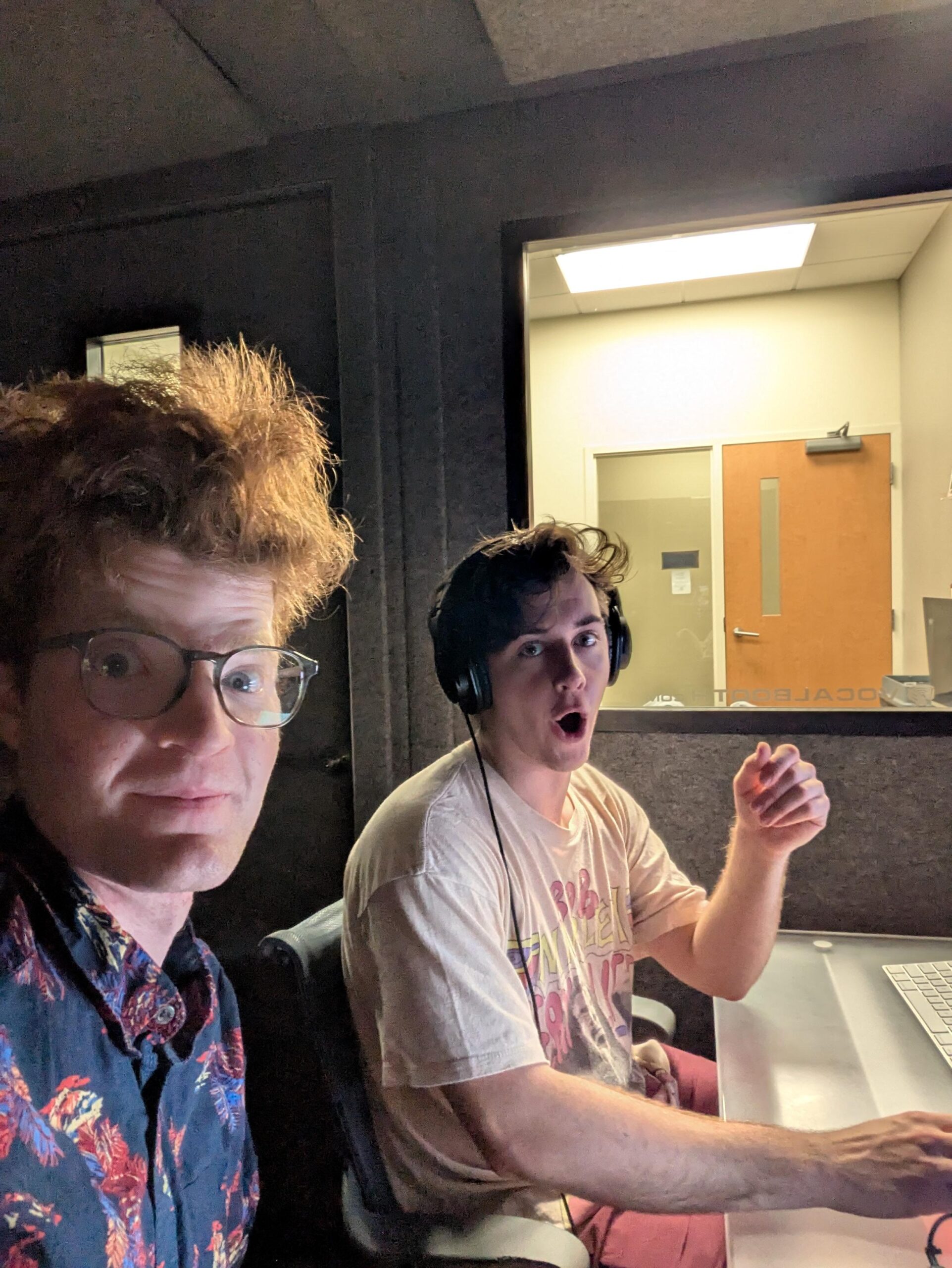
Michael Murphy has been tracked down! Huzzah! We recorded Episode 2 on Friday, April 18 in the recording booth in the basement of the HCC. It was a slightly different space but that is what worked with scheduling and Michael knew the systems well so that helped. We used Audacity to record the audio then exported it into my Google Drive so now I have it. The computer in the booth was an Apple computer, which is also unfamiliar to me so that was fun to navigate. Remind me to yell at Steve Jobs later for making things different (Just kidding, different is fine). Michael was an excellent help with all of that too. We spent like an hour talking about Preservation, and some other things. This one is definitely going to need to be cut down, but it was fun and Michael really added to the vibe, so shoutout to him for being awesome
Me and Michael Recording Episode 2, we had fun
Website Refining
I like the content on my website, but it looks slightly boring for my taste, I think it needs a little more sizzle. I also needed a logo that shows up on the web tab for it that isn’t the WordPress logo, so there’s still been a fair amount of touchup to be done, which I guess is a constant for improving anything. To try to find some sizzle I started playing with themes and wound up figuratively exploding my website into next week. That took some time to fix, which I eventually did, but WordPress is not always as easy as it seems I guess. After that I think I am going to keep what I have on that front, it is simple and easy to navigate, so why reinvent the wheel. I may change it later once I learn more but right now worrying about lots of other life things, I think simple is better for me. I did make a logo and a simpler version of it for the website icon, which I think turned out great. I used Canva to do that, it seemed the most effective way to go. That has now been added and I think the website homepage looks a lot better with just that. I also found a way to have the tagline as part of the title page, so now there is something saying what the website is in addition to the name. It is coming together nicely.
The Logo looks pretty good, at least in my opinion
Research and Creativity Day Prep – Part 2
I started making my presentation slides, and these are turning out quite a lot different than I was expecting. I am trying to have a healthy balance of process and actual research in it, because the research is the point of what the process has led to, and it has been fun to try to craft that. I think I have everything I need for them done, now I just need to practice the presentation. I am presenting Friday April 25 in the morning, so I have time. I also know enough at this point I should not need too many notes. I am excited for this, getting to share it with more people is super cool!
Next Steps
As the semester nears an end I have one ambitious goal beyond presenting at Research and Creativity Day. I want to publish Episode 2 before the end of finals week. We will see if that is doable as the end of the semester does its thing, added to the end of college and having a bunch of other life things. But all I have to do is edit and make the transcript, cite sources, and put it up. It did not take too long with episode 1 once I figured out how things work, and since I have already figured it out it makes it that much easier. I am going to try for that. Wish me luck, I’ll give one more update here later on.
Week 13 has crept up now, leaving only 3 weeks left to complete this project. No time to waste, so let’s get into it.
Fencing Up
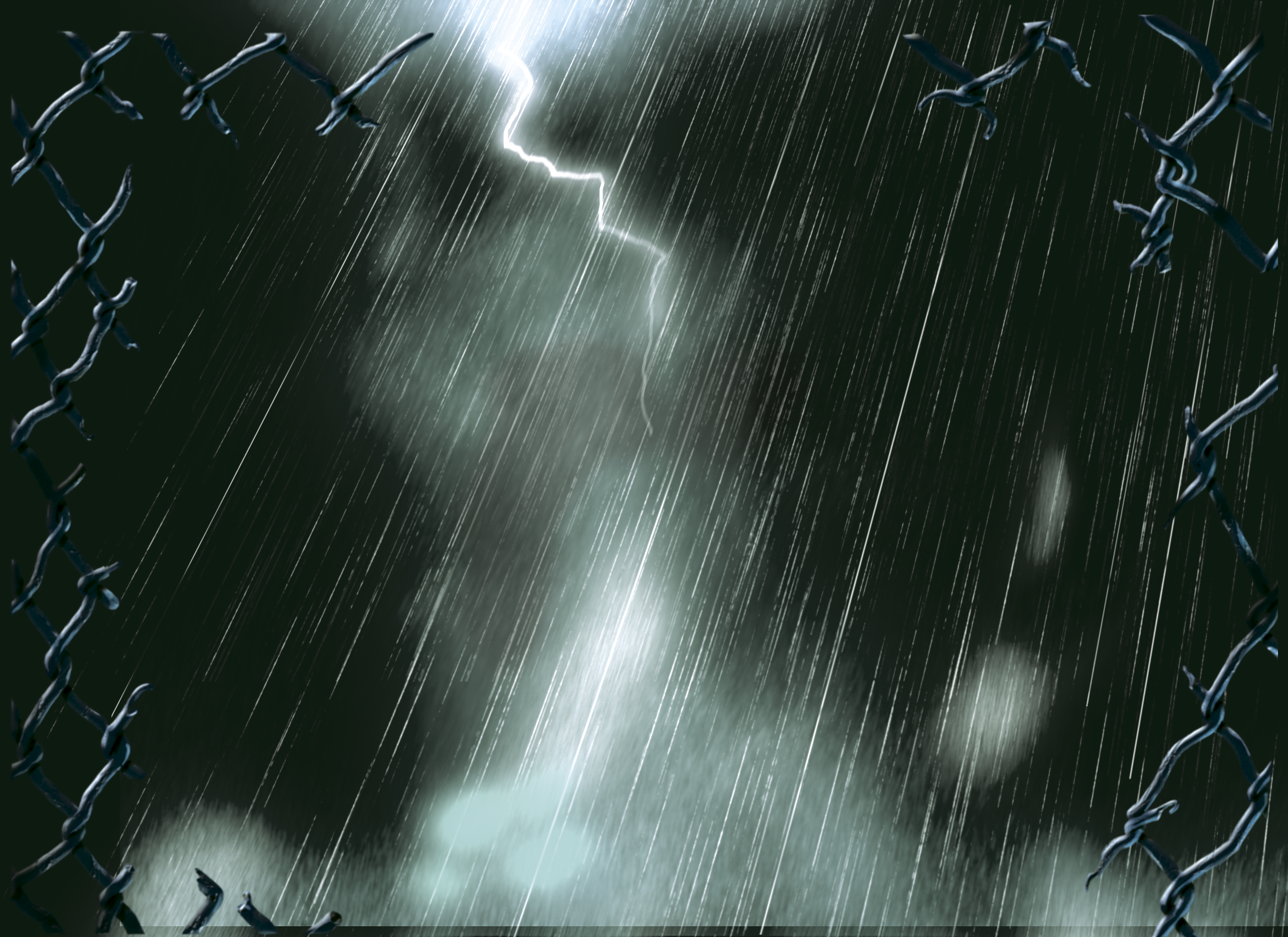
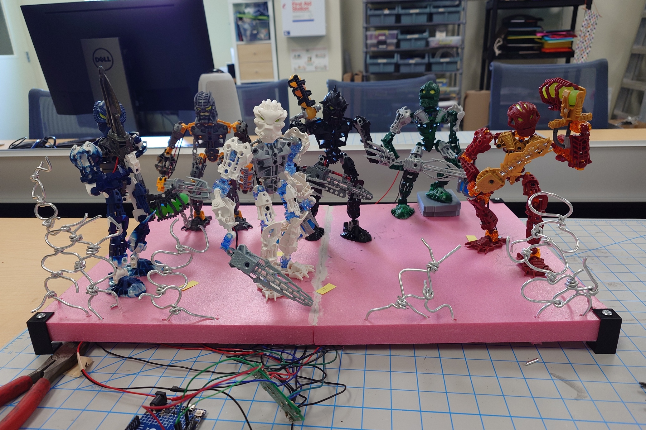
Continuing from last week, I immediately got to work making a few more fence sections. Once I was satisfied with the amount, I added them to the display in a way that would help sell the story idea that the Inika were storming the gates of the Piraka Stronghold.
These positions are in no way set in stone, especially because I’ll be removing them shortly to paint over them, but I think it’s a good start.
I also want to add bits of wire strewn about to better show that the fence is supposed to be broken open, but I’ll work on that after painting. Which speaking of…
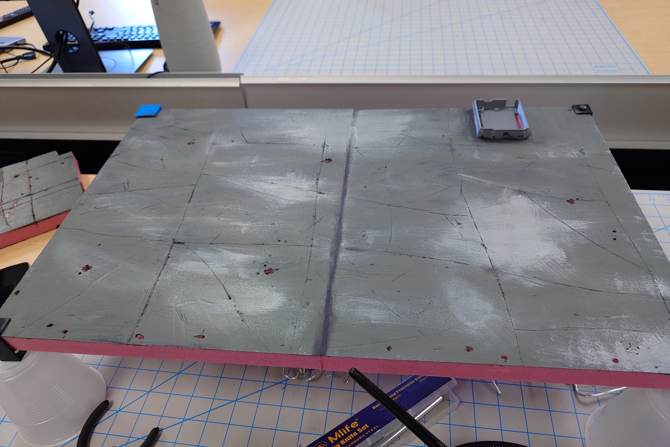
A Fresh Coat
It’s finally time, at long last.
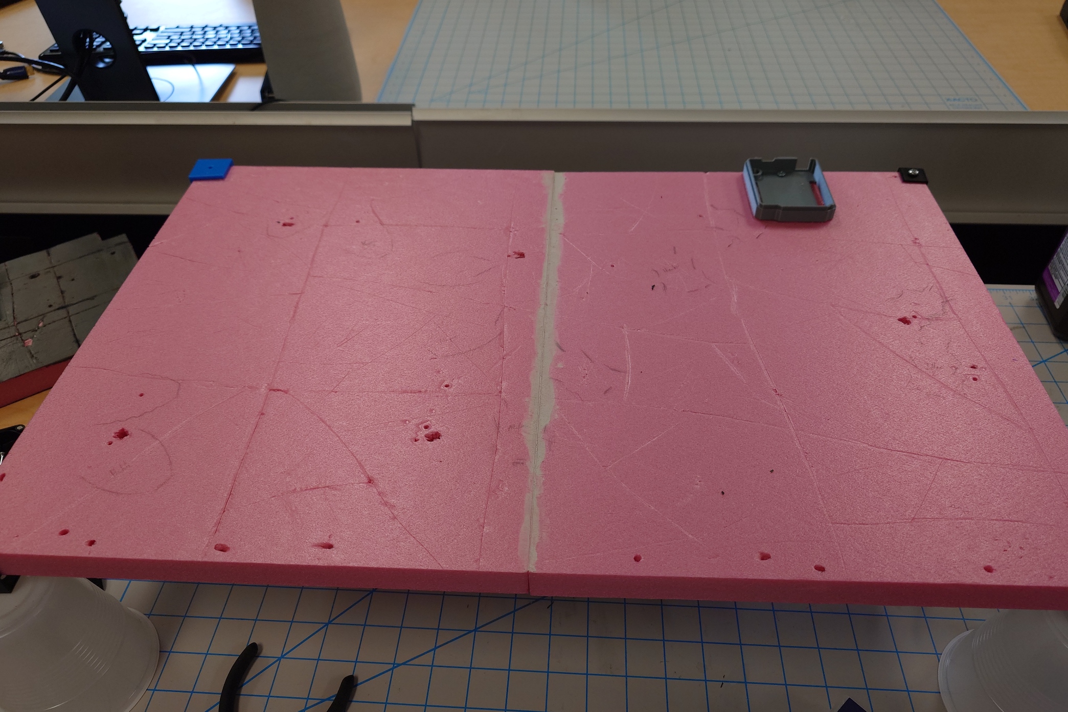
To get the base set up for painting, I lifted it up using some plastic cups, and removed the cables from each Toa underneath. Then, I removed the fence I just added, and finally, the Toa themselves.
Once that was all done, I scored the board with a knife to mark out the tiles, this time doing it by hand with more room for error, to really make it look like it was natural rock carved by enslaved Matoran.
I also made sure to give plenty of scratches, cracks, and other textures to show wear and tear.
Then, I simply just put a few coats of my primer mixture on it and waited for it to dry.
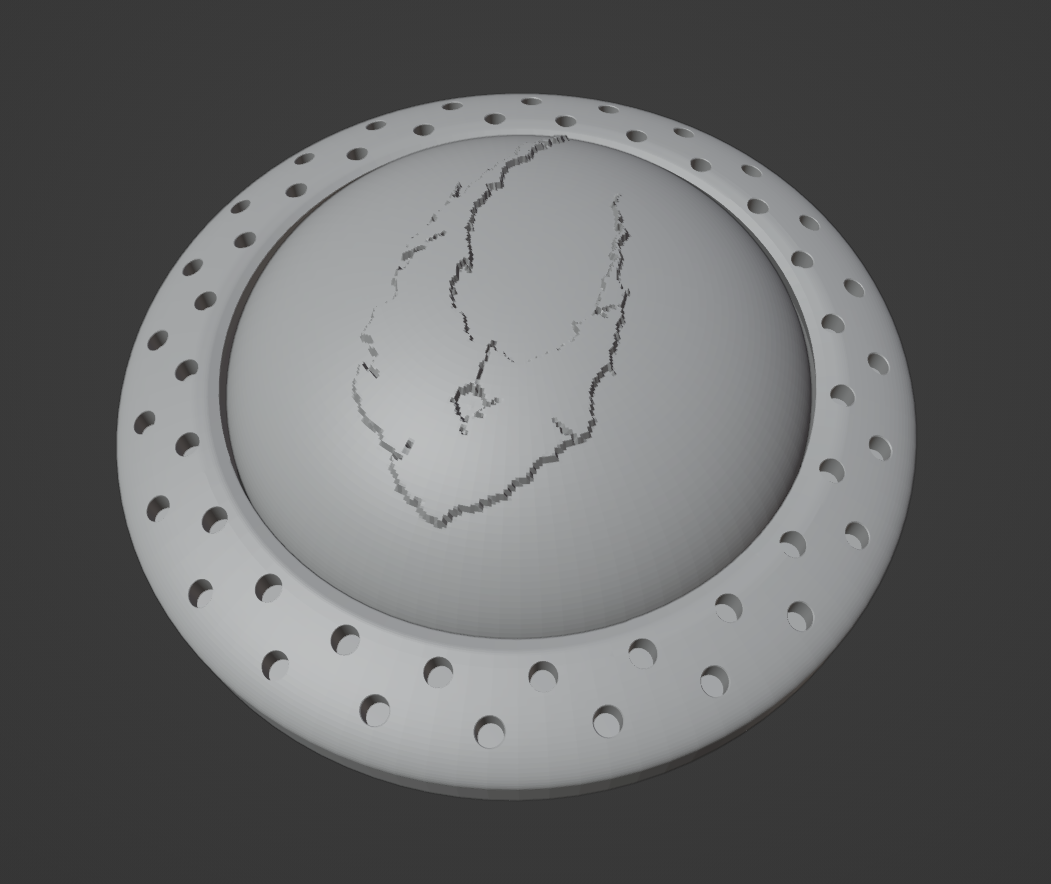
While waiting for it to dry, I began work on a button design, and I knew exactly what I wanted to do.
In the image below are some of the icons used to represent the first half of the 2006 year of Bionicle. The one of focus here is the Zamor sphere with the icon of Voya Nui inside of it, surrounded by some metal object.
It’s definitely clear by now what my intentions are. I couldn’t help but notice how well it would work as a button, so I got to designing a model for it in Blender.
I worked on it for a bit, but it was quickly back to painting as the layers dried faster and faster.
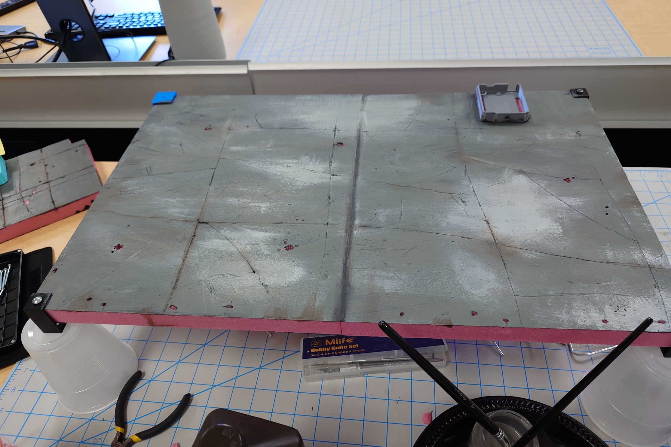
After applying the primer layer, I put a layer of grey over the entire board, and used a lighter gray to try and throw some highlights around it, to spice it up. I don’t think I did very well.
Nonetheless, I’m still satisfied with how it looks so far. The next step will be to apply a very small amount of the brown wash I used previously. I’ll make sure not to go overboard again on accident.
Which I think I did a good job at avoiding.
While I’m overall satisfied with the look of it now, before I seal it in entirely, I want to give it a day for my eyes to rest and refresh. I can always make adjustments now, but once I put the varnish on, that’s it, no more edits, so I want to make sure I have it right.
The Next Day
Coming back to it, I really, really like how it turned out. I did have to go over the lines a bit with a knife to redefine the edges, but I think I did great with this. So on that note, it’s time to seal it up.
I put some layers on, and continued working on the button design while I waited for them to dry.
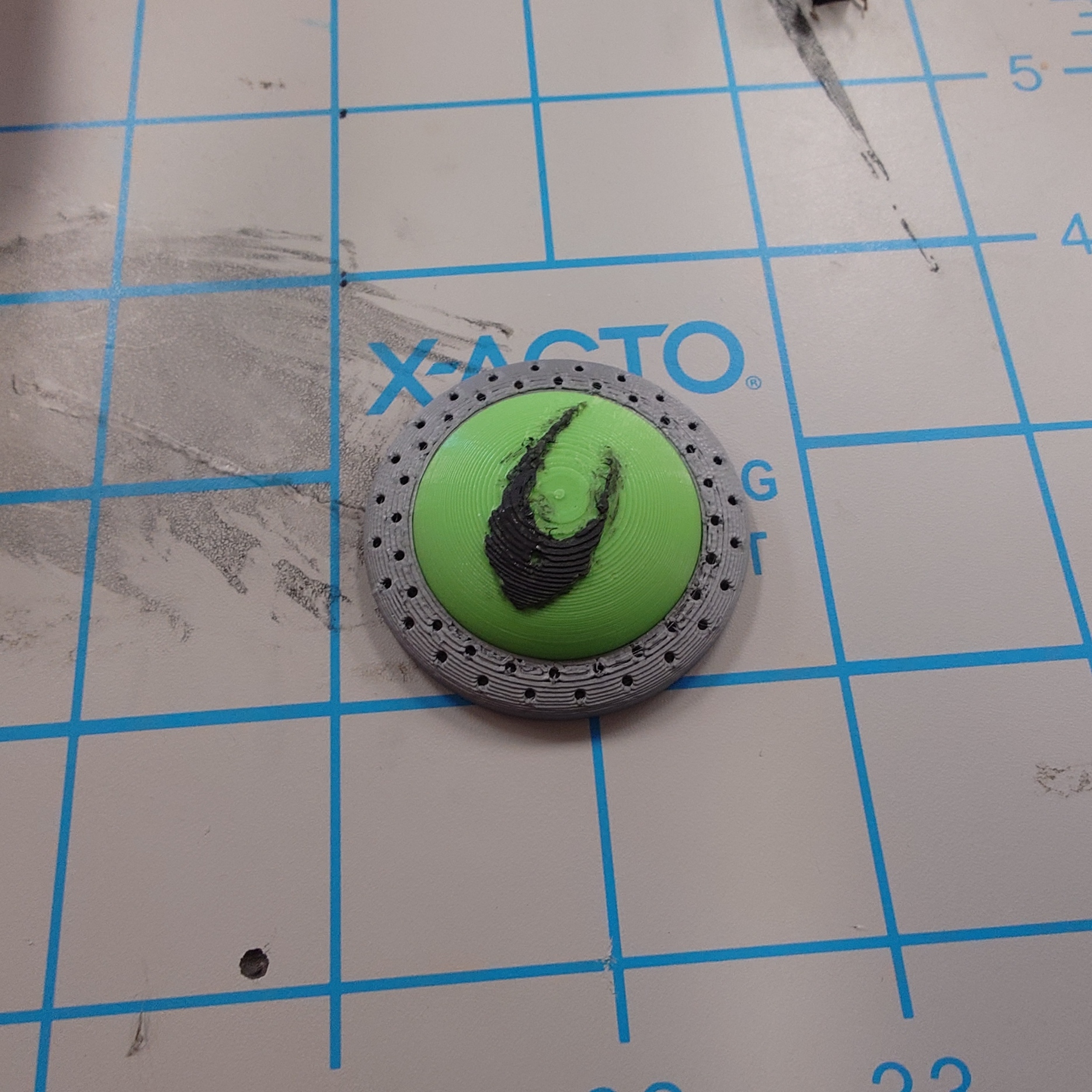
After some tedious copy and pasting, I came out with this result:
I gave it a test print and I’m mostly satisfied with the result.
I’ll need to make a few tiny adjustments to the size and specifics of it, but the overall core idea is there.
But with that short detour, the base has had enough time to dry fully, so I went ahead and started reattaching the chains and Toa.
While putting them back on though, there was a few things I found I need to address.
Minor Readjustments
First, Jaller desperately needs a coat of nail polish on his joints. He’s flying around like his joints aren’t supposed to stay attached.
The other thing that was bothering me is the composition of the Toa, again. Specifically, I didn’t like how similar of a position all of their swords were, as it became very noticeable with the lights on. It’s too late to change their positioning, but I can at least move their arms.
Specifically, I wanted to change up either Kongu or Matoro, and Nuparu or Hewkii, as the way they hold their swords are much too symmetrical.
For Kongu and Matoro, I decided to adjust Matoro so that his sword was raised up closer to his chest, rather than being parallel with the ground. I may adjust it slightly from here since now he, Jaller, and Hahli are all in sync with a similar pose.
But for now, it will work. Next up I looked at Hewkii and Nuparu. I readjusted Hewkii a little bit, but there wasn’t much else I could do with his current pose, so I had to, unfortunately, give in and allow Nuparu to two-hand his drill again. I just can’t deny that it makes him look so much more dynamic.
Like I mentioned with Matoro, I’ll probably end up making some more adjustments to the Toa, but I don’t think they’ll be worth writing down. But with this out of the way, let’s move on.
Display, to Play-set
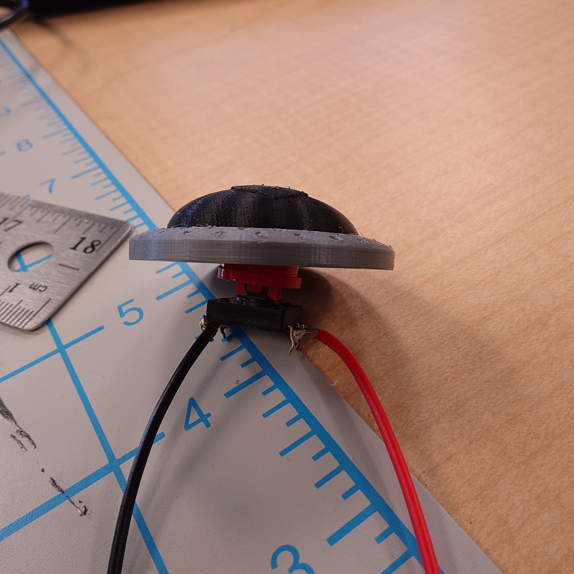
I want to finally get Kongu attached to the display, so I need to work on a button right now. I have the design I want ready to print, but I now need an actual, physical button for my button to press. Thankfully, the DKC has quite a few of those lying around.
I ended up choosing one of the larger buttons with a removeable cap, which means it’ll be easy enough for me to add that into my current design.
Although, it would be much easier to just attach my button to the existing button as is, which is the path I went down. I simply made a hole in the button to fit the other button into.
I still need to widen it a tiny bit, but this will work for the time being, as I am out of time for this week.
End of the Line
There is little time left for this project to reach its conclusion, so it’s a good thing that I also don’t have much left to do. I have received information about the printer I’ll be using, so I can begin work on the decals and get those printed next week, which will leave only the Plexiglass left to assemble. Of course, none of this until I print out the final design for my button.
It has gotten down to the wire, to the point where a single mistake can cause me to not finish the project. Thankfully, as I mentioned before, I will have much more time to work on this during the final week, if needed, but I would rather take the time to relax a bit if I can.
Regardless, I’ll rest up for now and prepare myself to bring this all together next week.
Week 12 at last. Only 4 more weeks to go, and I’m very excited to continue from last week, so let’s get right into it.
Follow the Light
A quick update before anything else though, I plugged Hahli in and left her light on over the weekend to stress test her light to make sure it wouldn’t fail on me at all, and thankfully, the light was just as bright as when I plugged her in. So thankfully, the resistors are doing their job in preventing the LEDs from burning out.
With that being said, let’s continue with the rest of the Toa. I chose Hewkii to be up next, just to work left from right. It took quite a bit of finagling to get the LED block to fit in his axe properly, but I eventually managed to reach a middle ground where, ideally, the LED block will flex into place. I also did a pretty poor job with soldering his cables, making a bit of a mess. But it did work.
Continuing the order from left to right, Matoro is up next.
His sword definitely gave me a bit of trouble, trying to get the wires to fit in. It did also open my eyes to a quite critical flaw in my LED block design. When the block sits on top of the lid, it actually ends up being just very slightly too tall for the battery compartment. This is why I had trouble with Hewkii’s axe as well, and why I had to squish the back plate down for Matoro as well just now.
Since I already have all of the blocks printed, I can’t say it’s worth reprinting them just for a slight height decrease, but if I truly cannot fit the block into one of the Toa’s swords, I’ll consider it.
Regardless, I continued with Matoro and soldered his wires together without incident.
I also found some thin silver wire that was part of some separate LED lights here in the DKC that happened to serve as a great way to replace the jumper cables to tie the lighting cables down to the Toa. From here on out, I used that wire instead of jumper cables.
However, one thing I took noticed of was that I would have a lot of trouble identifying whose cable is whose. I’ve already been using color coordinated cables, but the actual plugs directly underneath the Toa are still black and red, so I quickly just put some masking tape around each cable and wrote the respective Toa’s name on it.
With Matoro done, it’s up next to Nuparu.
His drill was particularly tricky to figure out where to put the holes. The best spot to do so would be on the underside of it, where the handle is, but due to how it’s shaped, his hand takes up the entire spot and leaves no room for cables to be routed. I thought of making holes in the battery compartment, but I’m almost certain that would bring a bunch of unforeseen issues, so I decided against it.
Instead, I opted to put holes on the top of the drill, where they could unfortunately be seen quite easily, but it was the best compromise I could make.
His process went the smoothest of any of the Toa so far, for the most part.
However, I couldn’t help but notice that his light was noticeably dimmer than the rest of the Toa, even compare to Hewkii’s. I believe this is due to me soldering the two red LED resistors on top of each other, and then on top of the power cord. So while Hewkii might only have the effects of one resistor, Nuparu probably is suffering from having the power of two resistors together, making his light dim.
So, I went back to the circuit board and tried to resolder to fix this issue. It took a good minute of reorganizing a ton of wires, but I managed to successfully get everything properly routed.
However, it didn’t seem to make any change in Nuparu’s light, leading me to believe it’s either something about his drill, whether it’s the way it faces or the tube being less transparent than the others, or that it’s the LED itself. Regardless, I want to move on and at least give the light a minute to “warm up”, so to speak, before I decide to replace it or anything.
Kongu would be next, but I want to wait a bit for him, given his unique situation, so I’ll skip ahead to Jaller.
His sword uniquely had an issue where some of the green light leaked through the front side, just above the button. I’ve never noticed this before, and I have no clue if it’s in the OEM light, but either way, I quickly solved the issue by putting some black electrical tape on the problem area.
The rest of the wiring process went fine.
This now leaves just Kongu left. He’s going to be a bit awkward to deal with just because he isn’t screwed in yet, but the process will mostly stay the same.
That being said, his crossbow immediately gave me a few issues. He shares the same problems that Nuparu and Jaller both had, where there isn’t a great spot to drill holes for the wires, and with the light leakage.
Thankfully, because his crossbow handle has a bit more space than Nuparu’s drill did, I was able to drill some holes from the inside of the battery compartment, and route the wires through them. The light leakage problem was also easily solved with black tape again.
After that, it was smooth sailing for the rest of him. Although, I opted to leave his cable dangling for now until I was 100% certain on where his final position would be within the board.
Establishing Boundaries
While I do still need to attach a button to the circuit board, I want to wait on that before working with it. The next thing I want to do is start making the iconic chain-link fence I’ve talked about so much.
For this, I’ll use some armature wire with an appropriate thickness. I don’t really have a plan on what to do beyond that, so I just decided to look at some reference images, and just try my best with it.
Try as I might though, I couldn’t seem to make anything out of it, and it was made very apparent that I had not a single clue of what I was doing. I couldn’t find any guides or tutorials on how to do this online, so I reverted back to asking Chat GPT for advice.
It originally suggested that I try a method of wrapping the wire around an object like a pencil to create a coil of sorts, and then to intertwine the coils together, which would work if I could easily twist the wire. Unfortunately though, it’s just too thick for that, so I had to reconsider.
I tried a few other methods, from trying to create individual loops to link together, to tying zig-zagged pieced of wire together, but every idea suffered from the issue of the wire being too difficult to bend, and even more difficult to bend into even shapes that would properly fit together.
I about gave up for the week, but I decided to ask GPT one more time if it could share some more video guides. While the advice it gave along with the guides didn’t really help me all that much, one of the videos suddenly made everything click.
Specifically, I saw this one by Sofia Bue on YouTube, detailing how to twist armature wire together for clay sculpting. I initially brushed it off since she was using much, much thinner wire than me, but there was one specific part of her method that opened my eyes.
About 40 seconds in or so, she showcases using a drill to twist the wire together, and the way she shows to do it is by taking one long wire that is folded in half on itself, rather than something like two wires put together and twisted at one end.
I very quickly realized that this could work for me as well. While the wire would still take effort to bend into shape, it would be much, much easier to keep the shape even.
I put it into practice, taking one lone strip of wire, folding it in half, making sure to keep a circular shape, and kept twisting it together, creating a general chain-link fence look.
It’s not perfect, but I’m confident it’s the best I’ll be able to get with the tools available to me.
But, once I have one link of the fence, I can modify it to look more damaged and busted by snipping some parts off, and then I can link multiple of these links together using a small piece of wire, which gets me a pretty good look, in my opinion.
It still hurts my hands a ton, even when using pliers to help shape it all, but I’m still glad to have found a solution. I made a few more of these links and set them aside, as I am unfortunately out of time for this week.
Moving Forward
First of all, I apologize for the rather light post this week. I had been very focused on being so hands on with the lights that I somewhat neglected to write this, although I also feel like there wasn’t much to write about, given how repetitive the tasks were.
I was also not a fan of how long it took me to complete the Toa’s lights this week. Due to some personal plans and obligations, I only managed to complete one each day, until Thursday in which I finished up Kongu.
Due to the time it took, I didn’t have enough to spare to work on this armature wire and discover the solution I did, which means I was unable to paint the foam base, so I am unfortunately behind schedule. This is also not to mention that I still need to work on the button function for the lights.
I only have three weeks left to complete this, so I really need to speed things up. Next week, I’ll apply the chain-link fence, and then paint the base after removing the fence and Toa temporarily. While I wait for the layers to dry, I’ll continue to work on a few designs including a button, some way to store the circuit board underneath the display, and some minor changes to the platform raisers on each corner of the base.
Once I have the paint put on, and I’ve printed out my various designs, I’ll shift focus to the Plexiglass and start working out how to apply it to the display. All of this will almost certainly take up the whole week.
But after that, I will also need to start creating the banner decal I want to wrap around the display. Currently, I’m still waiting to hear back from one group on campus who has a viable printer that I may be able to use. I must find the measurements before going all in on a design.
Ideally, this will be done in two weeks, but I am fully expecting that to just be blind optimism, given how there’s definitely so many other issues that will, without question, show up while getting all this done. I will just have to see.
In my previous blog post I explained how I was changing my code to show 3d visuals, that is no longer the case. My idea for how I wanted everything to look was posing problems for how to conceptualize 3d rendering, it will be something I return to in the future.
Since I have returned to 2 dimensions I have made much more progress towards shaping my visuals towards my original idea. Below are 4 iterations of the visuals, demonstrating a bit of how procedural my decision making is.
I began with the basic structure, all the planets I wanted orbiting the sun, then I begin emphasizing the orbits to make the planets more clear.
After that I simply tried seeing what would happen if I filled in the arcs tracing the orbits rather than just the lines, which I do like the look of, but the planets closer to the sun get lost in the bright stack of the orbits. Finally I added the traced arcs back in and I am happy with the look,, for now.
Below I have a draft of the visuals along with the music, this specific recording is a result of experimenting with the timbres of each notes, trying different virtual instruments, both sampled and synthesized. I am broadly pleased with the effect the visuals have to emphasize the music, though I am not entirely happy with either yet. I specifically need to refine the math I am using to determine the speed of Mercury, the innermost planet, around the sun, it does not seem to be lining up the way I want but that should be a simple fix.
And finally, my code, there is currently a lot of extra material that is doing nothing, I would like to implement a small explosion or expansion effect whenever a body passes the vertical threshold and a note is triggered. I am also considering adding a starfield in the background, normally these fields of light illustrate fast travel through space but I think a spiral would be a very nice effect, I could have multiple layers of stars moving at different speeds and different sizes to illustrate distance, I think this would add some nice depth. I will of course also be working more on the sound of the music.
At the bottom of the code is a table I wrote with the data I am using and the data I hoped to use. Unfortunately the solar system is just too large to have it all in one screen, the sun ends up 1 pixel wide, Pluto isn’t even on the screen and none of the planets are visible being tens and hundreds of times smaller than the sun, making every planet, tens and hundreds of 1 pixel.
The first thing I looked at on the Website is where I can add more content. An obvious spot was the main page, where I had one really bad paragraph that told nothing. I replaced that with a couple paragraphs about why preservation of baseball sites is important, and the complete quote that I bookended my conference presentation with in Gettysburg to emphasize the point further.
It also was recommended to me that I add an about me page, a lot of websites have them and they are a good way to know that the creator is legit. So I wrote up some stuff about me and my interests as it pertains to this project, some other background things like my National Park Service work, and linked the StoryMap again as well as these blog posts. hopefully that helps people take me seriously, not that they wouldn’t but it may show that my interest in the subject means I know something.
I also wanted to add pictures to the website so that it looks like something worth visiting. On the top menu, the only thing that actually had visual appeal was the StoryMap, so I wanted to fix that. I wanted to make it a more personal touch, so I used only pictures that either I or one of my parents took when going to baseball games or other places on various trips we have been on. It took a while to find the best options, I had to call my parents to see if they had some from years ago that were on an external drive back home, but I eventually got one for each page. I like how it turned out, I did have to play with WordPress to figure out how to make the picture visible, but even that was pretty intuitive and I gained something from it in terms of my knowledge of website building.
The Homepage for the website, its coming along nice
Podcast Recording Prep Work
Since this is a podcasting project, I do want to do podcasting too. My guest host for the next episode was once again busy when I was available to record, so I used the time I would have spent doing that fleshing out the outline for that episode a little more, which mostly involved polishing and clarifying a couple things in the notes, and fleshing out the outline for Episode 3 a lot more. Episode 2 is going to be the Preservation Overview to go with the baseball one that has been published. Episode 3 is where I am going to talk about baseball stadiums in various movies. While looking for things to talk about with that, I realized there are some movies that pertain to baseball but don’t actually use professional stadiums. Where do those sandlots and little league fields fit into preservation? I am definitely going to brush that in this episode, but it could be a topic for another one down the road, talking about community fields all the way up to the glamourous Little League World Series complex in Williamsport, PA.
I found movies where stadiums on my StoryMap were talked about to start the research process for this one, but then brought in some more modern stadiums later as a compare and contrast. I am also interested to look at cookie cutter stadiums to see how they are seen, and how they can fit into preservation. That could be yet another full episode too though. I have a lot of possible content for this episode, now I need to make it flow nicely in an outline that I can understand while recording.
Presentation Prep (Part 2)
The last thing I worked on this most recent stretch was the materials for Research and Creativity Day, which is coming up later in the month. I have to present for this fellowship, but I probably would anyway because its such a cool project and I want to share it with as many people as possible.
The first step to getting to present at Research and Creativity Day is writing an abstract, and luckily I wrote a few possible abstracts for the Middle Atlantic Archaeological Conference that I combined for the final product, but I kept the original drafts so I can use those as a guide for my abstract for this. I picked the one that talks less about the Negro Leagues and more about baseball overall, since this phase of the project is bringing all of the things I have found about the Negro Leagues into the context of the rest of the baseball world. I am making a few changes to it to fit the scope of what this phase of the project is covering, so hopefully it winds up being good and catching people’s attention. It is a challenge to make it concise and still make sense, but I got some practice with that preparing for MAAC, so I feel confident I can do it.
The different thing about this one is that I am building a presentation off of my research materials and not so much off a paper. I did build my paper for MAAC off of the StoryMap, so I know it is possible, but it will be a slightly different approach that I am going to have to play with a little bit. I think rather than having it about the content, I am going to talk about the process and journey of the project and what I have learned through that about different tools I have tried to use. This phase of the project has been the most informative to me in learning new systems, so I think that is a good thing to have included in it. I am still going to have a lot of baseball content, as that is the point of the project and that is what I want people to take away. I will have a link to the website at the end of the presentation to allow people to access more content if they want to.
Next Steps
I don’t really have many new things to do. I am going to find a time to record episode two this round. This will happen. If it doesn’t happen, that is not ideal. So it needs to happen. Otherwise I am scheduled to record an interview for the DKC Creators podcast this week, so that should be fun, and I will be finishing up prep for Research and Creativity Day. Simple, easy (Schedule alignment permitting), and fun, until next time, wish me luck!
Week 11 already. As I suspected, the last two weeks went by extremely quickly, so I expect the next two weeks to be slower, which is good as I have some of the biggest pieces of work to do here.
My supplies still haven’t arrived yet, but I expect to have access to them within the week. In the meantime, though, I am limited as to what I can work on.
Back to Base-ics
Have I used this chapter title already? I don’t think so, but I also don’t want to bother looking back at my posts to find out.
Regardless, I let the painted foam sit for a while, but I still wasn’t happy with how it was looking, so I got Shannon and Cartland’s thoughts on it.
From my discussions with them, I decided that for the real display, I’ll make a couple of changes to my strategy. Firstly, I’m definitely toning down the brown wash, as I previously stated I would do. Carland specifically mentioned that my base reminded him of the Fallout games, which is not a bad thing at all, but not what I’m going for, and I believe that is due both to the heavy brown, and overall dark color scheme. Which brings me to my next change.
I’ll use a mixture of my grey paints to make a grey that’s lighter than what I have now, but not as light as my light grey paint on its own. I think this will help make the platform look less dirty and apocalyptic overall. Plus it also gives me extra room to add some dark grey detailing if I need.
Finally, I’ll also opt to carve the tiles by hand without the use of a ruler. I believe the reason the entire thing looks so off right now is due to the contrast between the super neatly carved tiles, and the extremely dirty paint job on them. My intention is for them to look like rocks, carved by the Matoran that the Piraka enslaved to build their stronghold, but the lines are much too neat to have that effect. So instead of using a ruler and knife, I’ll just use a flat-head screwdriver and some elbow grease.
Alternatively, if I want to keep the straighter and more properly carved look, I could opt for smaller tiles, but I’ll at least see how I feel about the larger tiles first.
Now, as eager as I am to start this now, I must hold off. I need to first get the cables for the Inika’s swords and figure out where I need to create holes for them in the foam. But since I don’t have the cables, the most I can do for now is position the Toa so they are ready to recieve.
Nailing it Down
I grabbed the display base and positioned the Toa on it, following the general pattern that I had established much earlier, but I did apply a few changes:
First, Jaller and Nuparu’s poses got changed slightly. They kept getting knocked over by accident when I would go to grab another material, and I ended up getting some poses I liked.
I switched Kongu and Hewkii’s positions for the sake of composition and color coordination. I have not mentioned this in depth before, but each Toa shares their sword light color with another in pairs. Hewkii and Nuparu have red lights, Matoro and Kongu are blue, and Jaller and Hahli are green. With the composition I had before, Nuparu and Hewkii were very close together, which not only made them blend in with each other because of their dark color schemes, but I also didn’t think that having their two red swords together would look very good.
I also swapped Matoro and Nuparu’s places to keep the light composition spread out.
Lastly, I made some minor adjustments to the overall composition of the team that I will go into more detail with next.
Despite all these photos I’ve taken, my skill to keep subjects centered and light levels balanced is very poor.
I tried to follow the positioning I established earlier, but I ended up needing to move things around a bit. My biggest struggle was keeping the Toa spread out enough so that they had their own space to breathe, while not leaving massive, awkward gaps between them. I think if I had unlimited funds and time, I would widen the XPS boards just slightly which would help greatly. But alas, this is the best I think I can do.
To help guide my placement, I used some bright green slices of a sticky note to act as a stand in for the little name plates I want to add later, my thought being that I should have enough room to clearly see each of the name plates.
I also left some room around the front edge and corners so that I could easily install the chain link fence for added decoration. I expect that I will need to create some extra foam debris to scatter around the area too, but I’ll leave that as a treat for myself if I need a break from any of the other work.
But with everyone generally in place now, I grabbed some screws, and started putting them in place, save for Kongu. Before I get him in place, I need to prepare the board for its final resting place.
Cable Management Simulator
What perfect timing for this too, as my cables and paint varnish have arrived, so I can finally sort this out, finally.
First, I carved holes in the foam for the wires to connect to the board. Then I screwed the bottom of the board case in place to make sure it would be aligned.
The next thing I needed to do was get some experience with the new cable connectors, as they are extraordinarily tiny.
It’s so small that the LED legs barely fit, with a good chunk of elbow grease and even then, only sometimes, in a specific direction.
Unfortunately, it’s too small for me to use, so I need to discuss with Cartland about it. I found replacements that should be closer to the original size, but we’ll have to wait on them.
In the meantime, I figured it would be helpful to start prototyping my final design for the cables. How will I connect them to the Arduino? How will I spread the power out among the Toa evenly? Questions with answers I need to find.
Power Problems
The biggest issue I faced while testing the lights before is that I don’t know how to evenly distribute the power from the Arduino board between them all. It’s a whole complicated system of wattage, voltage, amplitude, and just having a good set up. Since I don’t have the time to take a full class on all of these systems (although I probably should in the future), I relied on an old friend to help me out.
ChatGPT instructed me to use some resistors to regulate the flow of power between all of the lights. Since the red lights use less volts, they apparently have a stronger draw on the overall voltage, if I’m understanding it right. The same applies to the green and blue lights, of course, but to not as strong of a degree. Having resistors in my setup will help limit how much voltage each LED diode takes up, and will also help increase their lifespan and save them from burning out.
I had quite a journey while setting it all up. From digging through thousands of resistors, to burning out some lights, to occasionally blinding myself, and having to worry about limitations I wasn’t even aware of.
For example, I found out that one output pin on an Arduino board has a safe limit of 40mA, but each LED diode draws 20mA alone, or even up to 30mA for green ones, so I needed to split up the power distribution between multiple pins.
It was quite a lot, and too much to go through here, but this is all to say that I spent multiple hours to get this slightly more organized prototype:
Ideally, this same set up should be stable even when I switch to the permanent, longer cables, but we’ll have to see.
I also had it help me set up a button to activate the special flashing sequence I created previously. As much as I would like to show it off here though, adding that gif very nearly killed WordPress last time, so I will hold off until I have time to kill, or something.
The next thing I need to do is translate this prototype into a final design. I unfortunately can’t use the bread board as it is now because it simply just won’t fit within the space underneath the display, so I’ll need to choose something thinner, and also more secure.
The idea I have for this is to use a perfboard again. It will be easy enough to solder wires to it and create a connection between them all, while also keeping it small enough to fit basically wherever I want it to.
I was initially worried about how I was going to secure the cables to the Arduino board, since the jumper cables I’d been using kept getting pulled out at the slightest bit of force, but thankfully, using standard DuPont connectors are secure enough on their own.
With the basics figured out, I got to work designing and putting together my own custom circuit board.
Feeling the Connection
Just in time for this, my new cables arrived (along with the armature wire). I tested them, and thankfully, they fit much, much better than the previous ones, even if they are a bit bigger. These will be much easier to work with.
To double check the fit of them, I went ahead and printed a new LED block, this time in full black with a higher detail level.
While it printed, I did a quick bit of experimentation with the cables. I knew at one point or another, I would need to extend the length of the wire, because there would be at least one Toa that wouldn’t be able to read the circuit board, so I wanted to get some practice with fixing that.
The easiest way to achieve what I want, while keeping it low profile, is to solder cables together. I looked up some tutorials and videos to make sure I was doing it correctly. I decided that I would put two female connectors together, that way I could plug one side into a male connector to get even more length, and to get some use out of the other connectors that came with the cables. After a bit of time, and a handful of nervous patience, I got some nice results:
I plugged the ends of the male connector into the Arduino, and put an LED in the open female connector, and it worked as expected.
Right on time, again, the LED block finished printing. I wanted to use this long cable with it and Matoro’s test sword, but I quickly realized there was no way to run the cables through the holes I already had in the sword, without removing the solder I just applied. I’m glad to have made this mistake, so I know for the future.
Nonetheless, I just fit a different female connector into the block, along with an LED, and then in to the sword. It took a bit of modifications, mainly due to the poor placement of the holes in Matoro’s sword, but it does fit.
So with all of this in play now, I suppose it’s time to finally route these cables into the display.
Strange New Power
Since I have a plan in mind for the circuit board, the easiest thing for me to do will be to set up each Toa’s sword one by one, that way it makes it easier for me to track my progress and what needs to be done.
First up, I decided to start with Hahli. Partially because I have a backup sword on hand for her in case something goes wrong, and partially because her cable will need to be the longest out of all of the Toa.
The first step was to find out where I need to place the holes in her sword to hide them the best. I managed to find a good spot, but I am still incredibly nervous about making holes in the Toa’s swords, but there’s no more running from it.
After a mild panic attack, and a lot of willpower, I managed to get her LED block set up in place, with the wires.
I place her sword back on her hand to see where I wanted to route the cables, but as expected, it’s too short already, so I went ahead and soldered her cabled with another connector, as I had practiced.
It went quickly and turned out well, so the next step was to actually make a hole to turn the cable through. I chose to do it in the gap of Hahli’s foot, since it happened to fit so well. While organizing the cable too, I also decided to take some advice from the Jaller display, and wrap the cables around Hahli’s body, securing them with bread ties (I still don’t know what those are called).
Since I didn’t have any of those ties on me, I opted to use some jumper cables for now to at least get an idea.
This is about as hidden as I’ll be able to get the cables, and I think I did very good with it.
I wanted to quickly test out her lights again, so I plugged the Arduino in place and shoved the circuit board under the display. Unfortunately though, even with the extended cables, Hahli’s cable still cannot reach the circuit board, meaning I will have to solder some more extensions on, which is no big deal.
Once that was taken care of, everything was working exactly as I wanted it to, meaning Hahli has the honor of being the first Toa Inika to have power to her sword.
Weekly Conclusion
And with that, I am way out of time for this week. It went by super quickly, but I managed to get a very important step done. My work here today has set me up to be primed to finish the lights next week. I imagine that will take a day or two.
After I finish the lights and figure out how I will deal with the circuit board, I’ll turn my focus to the top of the board once more and work on the chain link fence, and once that is all set up, I will be ready to finally paint the base of the display, which will then let me move on to applying the Plexiglass.
There’s still lots left to do, so I will rest and recuperate to make sure I’m ready for it all next week.
It’s now week 10, which means there’s only 6 weeks left to go on this semester. Time is quickly running out, so let’s get started.
Tactical Espionage
I want to immediately get started on disguising this Arduino board, since I’m expecting it to be quite a process.
The idea I have right now is to just try and blend the edges of the box with the base of the terrain, so it helps hide the unnatural shape of it. My intention is to make it look like a piece of rubble, possible from the wall of the Piraka stronghold.
While I work on the design for this, I’ll be printing the case again but in a different color that should match the color I’ll paint the foam around it, since the bright blue makes it stick out a bit much. The best color that was available was one just called “Silver”.
With it printing, the first thing I need to do is refine my cutting technique, because, as I said in the last post, I have been unable to get any clean cuts in the foam so far. For this, I just looked it up online. There are a great many guides that suggest using tools that I don’t have access to, such as a hot wire, or jigsaw, but I did find this video on YouTube that shows off how to achieve clean cuts with a utility knife, which I do have access to.
In the video, he suggests using a square to help with getting straight cuts. While I don’t have one as fancy as the one he uses, the DKC did have a smaller one that would get the job done. I followed the technique he used in the video and…
It came out much, much better than any of my other cuts have. It’s not perfectly straight, but that’s fine for my use case. I don’t know any minerals in nature that have perfectly straight edges anyway.
I continued cutting bits of the foam, going nice and slow. It’s a tedious process, but I don’t have any other choice than to put up with it for the sake of quality. I kept at it until I had a bunch of rocky-looking chunks.
I’m quite happy with how these turned out. My process for creating them was to literally just cut the foam down into an appropriately rock-sized chunk, and then just keep cutting in all different directions until I had an appropriately rock-looking rock.
They’ll start really coming together once I paint them, but there’s something to do before that. Something I’ve been especially excited for. To really sell the rocky look, I can put some texture on the foam.
Now, depending on the material that is being created, the texture process will vary quite a bit. But the best way to get a rocky texture?
A bunch of actual rocks! I quite literally went outside with a baggy to the nearest gravel path, and just picked out a few samples (that I will return once I am done).
Now comes the fun part. I put all of the foam rocks into a separate baggy, placed them in a small bin, and then dumped the rocks into the bin with them. Then, I closed the bin and just gave it a good shake. And then after the shake, I took out each of the bigger pieces and patted them down with some of the rocks for some extra texture.
Try as I might, I can’t get the texture to show up on camera, unfortunately, so I won’t bother uploading a photo of the result. I will, however, get a proper photo once I paint the rocks, which is up next.
Edgeification
To paint the rocks, I first coated them with the classic paint and ‘podge primer combo. I went over each rock once or twice with a thin layer, which really helps them look more like rocks.
We’re not done with them though. To help them blend in more with the new silver case, I’ll give a couple of layers of grey paint to each rock once they’ve dried.
While waiting for them to dry, I started work on the platform raiser design I had in mind. It took a bit of work and was a slight hassle, but I came up with this in Blender:
My idea for it is to be a clamp of sorts. The top section has enough room for the foam to slide into (give or take; the thickness of the foam varied by about 2 millimeters), where a bolt will fit through, and then be tightened with a nut. The bottom section gives 15 millimeters of lift, and also has an extra hole so that I can tighten another bolt into the plexiglass that I plan for this to sit on top of.
To make sure it worked properly before going all in on it, I printed a test design of it, which gave me time to focus on the rocks again.
I gave them a coat of grey paint, making sure it wasn’t too dark or bright by mixing the two grey colors I had. While I didn’t intentionally leave the layers very thin, I think doing so helped make them look much better.
I think they could use a bit of extra wear along their edges, but I’m not certain how to go about doing that without exposing the pink foam underneath. So, at least for now, these will do nicely.
While the rocks are done though, I still want to toy around with painting the base board. I mentioned last week that it was looking a little bland for my tastes, and the first idea I’ve had to fix that is by carving some tiles into it. My thought process is that, because I want the Toa Inika to be storming the Piraka stronghold, it’s not unreasonable to assume there would be some sort of tiled floor.
I started by scoring some shallow lines using a ruler and knife, keeping the tiles generally wide.
From there, I took a random flathead screwdriver and ran it through the lines a few times to roughen the tiles up a bit. After that, I randomly started recklessly using the head to add some more wear and tear to the tiles, and pounded the handle somewhat randomly to add a bit of texture.
I made sure it especially put some extra wear on the corners were four tiles met up, but also tried to keep the distribution of damage somewhat even. I don’t think it was the best job, but the fact that I wouldn’t have painted the foam yet comforts me a bit. I expect that all of the visible foam in the cracks will be hidden by the black primer layer on the final product.
Borrowing again from Adam’s arsenal, I tried applying a brown wash across the tiles to really help add some grime to it all. To make the wash, I simply just took a bit of brown paint and mixed it with the nearest water-like liquid I had on hand, which was the hydrogen peroxide I’ve been using to dissolve the paint off the brush.
I tried keeping a decent balance between having it super watery and not very watery at all.
While it definitely helped a bit, I absolutely overdid it. I ended up not using enough peroxide in my mixture, and used too much of the mixture overall, causing me to have to spread it out a lot more than I intended.
I don’t think it looks bad at all, but it definitely is a lot grimier than I was thinking. I’ll leave it for a while and come back to it after some time has passed and see how I’m feeling about it. If I still don’t like it, I’ll try adding a bit of a light grey wash along some edges and corners to try and balance it out. If I still don’t like that, then I’ll know to use much less of the brown wash in my final product.
While I simmer on it, this gives me the perfect time to focus again on the platform raisers.
Building the tallest tower…
Looking at the printed result, it came out a bit differently than I expected.
I purposely made it thick for the structural stability, but this is much thicker than I was wanting. I also made the bolt hole too small and had to expand it a little bit to be able to fit the bolt through, and even then…
The bolt is too short to reach the other side, and even if it was, I wouldn’t be able to fit a nut in that tiny little space. I had to modify the design.
A little bit of tweaking later, and I got this much nicer looking support:
I made sure to widen the hole and thin the entire piece up overall. It definitely looks a bit nicer, but even with these adjustments, the bolt doesn’t have enough room for a nut underneath.
For this problem, I’m thinking I’ll just find a differently sized bolt, assuming the rest of my design does work. Since I’m fairly confident in it, I went ahead and printed three more of these designs to try out on the real base.
Printing all of the supports out, they do lift the base up enough as I hoped, but there is one issue that has reared its head. Despite the foam being advertised as the same size when purchased, it actually varies very slightly, so two pieces won’t have the exact same measurements. This normally isn’t a problem, but because I’m relying on it to be symmetrical in all spots, I’m subject to it.
In three of the corners, the designs fit generally well, even if I’m still not able to attach a nut to them. One corner is definitely a lot bigger than the rest, but I can at least squeeze it down. The same cannot be said for the last corner that is much smaller than the rest.
I tried my best to add a nut to an extra-long bolt, but no matter what, it didn’t stop the support from being shaky and loose.
I tried every other idea I could think of, between using washers, different sized nuts, and even creating a clamp design, but none of them worked at all. The only idea I have left for now is to just adjust the design I have so that it fits specifically on that corner, but I really don’t want to do that.
For now, I’ll leave it as is and come back to it when it’s time to install the plexiglass, since I still need to account for that no matter what design I go with.
Time’s Up
Unfortunately, I have to leave it all here as that’s all the time I have left for this week. I made some progress, but not as much as I’d like, especially considering that I still don’t like how the painted tiles look still.
My cables are supposed to be coming in any day now, so my first priority will be to get this paint job finished up so I can apply it to the main base and then get the Toa in place and ready to connect to the Arduino.
After that is all done, it will be time to deal with the Plexiglass. I have a plan created, but I still need to make sure it is within budget. This will definitely take me to the end of next week.
But with all that being said, I need to start cleaning up here.
In order to prepare for working with 3d objects (my plan for representing the planets), I wanted to familiarize myself with the tools in p5.js that enable 3d. As it turns out, they’re rather simple. You must simply declare the canvas with an extra argument (WEBGL), and then you may call commands such as orbitControl() which enables movement in 3d via the mouse.
To practice the placing of objects in 3d, I played around with the code snippets provided in the documentation. Firstly, it’s just a sphere comprising rings of cubes.
I added the ability to make concentric layers, here is 1 internal layer.
To ensure this looks nice I am scaling the size of the cubes, the distance between the spheres of cubes, and the line thickness of each edge of the cubes.
And at 9 internal layers, 10 concentric spheres in total, some interesting shapes and patterns emerge.
Below is the code that was used to generate these images. I achieve different results by tweaking the values I have passed into different functions, chiefly the scale of the main sphere and number of sub-spheres passed into drawCubeSpheres(50, 10); 50 being the size used for all of these images, and 10 being the amount of spheres in these final two images
function setup() {

    createCanvas(1150, 750, WEBGL);

    angleMode(DEGREES);
    noFill();
    stroke(32, 8, 64, 255);
    describe(
        "Users can click on the screen and drag to adjust their perspective in 3D space. The space   contains a sphere of dark purple cubes on a light pink background.");
}

function draw() {

    background(250, 180, 200);

    // Call every frame to adjust camera based on mouse/touch

    orbitControl();

    drawCubeSphere(50,10);

}

function drawCubeSphere(scale, numSpheres) {
    scale = ceil(scale);
    // number of spheres of cubes
    for (let i = 0; i < numSpheres; i++) {
        // Rotate rings in a half circle to create a sphere of cubes
        for (let zAngle = 0; zAngle < 180; zAngle += 30) {
            // Rotate cubes in a full circle to create a ring of cubes
            for (let xAngle = 0; xAngle < 360; xAngle += 30) {
                push();
                // Rotate from center of sphere
                rotateZ(zAngle);
                rotateX(xAngle);
                // Then translate down (eg.)50 * 8 = 400 units
                translate(0, (scale * 8) / (i + 1), 0);


                strokeWeight(scale / 10 / (i + 1)); // scales down
                // strokeWeight((scale / 10) * (i + 1)); // scales up
                // strokeWeight(5); // constant
                box(scale / (i + 1)); // scales down
                // box(scale * (i + 1)); // scales up
                // box(scale); // constant
                pop();
            }
        }
    }
}
What I’m working on next in this area is tracing 3d objects around a circular/elliptical field. This project is involving more math revision than I anticipated but i do welcome the process of refreshing my geometry.
Music
I must admit little progress has been made the last couple of weeks due to my failing to schedule time experimenting with music, I do however have a demonstration of the music in its starting state. I am working in Bitwig Studio as opposed to Ableton Live because I’ve found it much more stable and crashes far less often. The video shows one track per planet/celestial object and in this current state each orbiting body is introduced slowly to get the listener accustomed to the rhythm before further complicating it with more and more cycles of notes.
This week I will be playing more with the actual sound or timbre of each planet as well as trying more structures that the piece might work in.
I have figured out how to make the top menu look the way I want it to, and link directly to the StoryMap! It now has that, and there is also space to post the First Episode of the Podcast, which operated smoothly. I went into the road trips maps page and hyperlinked actual words with the links instead of just having the links by themselves to make it easier to know which one is which, and now all I need to do after posting Episode 1 of the podcast is add some pictures to make it interesting to look at. I think I am going to use some from my own travels for the pages, at least to start. It gives a more personal touch in my opinion. I just need to go through and figure out which ones are best. It actually looks pretty good right now I think, and I am excited to see how I can make it even better!
Final Podcast Edits and Publishing
I have cleared space on my hard drive now that I have access to my external drive again, so there is plenty of computer space to save the audio files I need. I figured all of that out and put the file into SoundTrap. I also looked for some other sounds to add in as opening and closing parts, I wasn’t trying to be too fancy for the first episode, just wanted to have something to bookend it for now. I like the sounds I found, but I do also think that as I learn more with this those sounds may change from episode to episode while I figure out what I like and what listeners like too. Experimentation with that seems like a good approach. To start out I went with the classic ballpark organ cavalry charge to open and the mid inning organ sound that also plays in ballparks to close. These are both really fun to hear, so hopefully it connects the ideas to the places for people, getting that preservation vibe. With that the only thing I had left was to put citations in the transcript, which I used Microsoft Word to make. I did have to do some editing and brush up after putting the audio file in the document, but that was minor compared to having to type it all out myself, although it helped me be more conscious of enunciation, which I think helped me in Gettysburg (more on that later). Anyway, after putting all the sources with the information I got from them, I copied everything into the draft of a post on the website, embedded the audio of the episode at the top, and now it is published on website. I hope it is good, I know I can improve but it is decent I think for a first real try outside of a class assignment.
Middle Atlantic Archaeology Conference
Gettysburg, PA. March 19-23. That was a long weekend. My Paper Presentation for my StoryMap project was at 8:50 AM on March 21, so we (Mary Washington Archaeology people) got there on the evening of the 19th and explored the battlefield and town of Gettysburg on the 20th while some workshops were happening as a way to take my mind off the presentation before it happened. I woke up on the morning of the 21st really nervous, which was a common feeling in the weeks leading up to it as I prepared for it. I guess jitters are normal, but as I went into the room where the presentation as happening I could not sit or stand still until I got up to talk. I led off the session, so that was nice to get it over with, and as soon as I got up there and saw at least a hundred people in front of me, I calmed down a lot. I would have thought that would freak me out more, but seeing that manty people there to hear me talk and see what the Negro Leagues were all about and why their ballparks matter, that fueled me. I started the presentation and just rolled through it.
Me at the beginning of my presentation, that was fun!
I spoke really well, which I guess makes sense because I spent so much time on it, I knew what I was talking about. I was also reading the paper out loud instead of having talking points, because that was what was recommended as the normal thing to do and since it was my first one I thought it was better to go with that option. I did really want to talk off an outline and have more audience engagement, as I do when I lead tours for places, but I see why this one had to be done like this too. After it was done I got really positive feedback from so many people. They told me how cool it was, asked where to find more information, offered ways to improve or add to the project, and just gave so much overwhelming support. I could not have asked for a better first conference presenting experience.
The crazy thing is, all of that was not even the best of it. Saturday evening, the 22nd, there was an awards ceremony where they announced the winners of the student paper/poster contest. There were three categories, one for graduate papers, one for posters, and one for undergraduate papers. I was surprised to see who won the undergraduate category
Me with the other winners of the Student Research contest and the organizers, that was a neat surprise.
I guess my hard work paid off. I am really proud of it and definitely excited. I was told there would be an opportunity to publish the paper with some fine tuning because I won, so I am going to see where that takes me if it is something feasible.
The conference ended with a CRM Skills workshop on Sunday, we dug Shovel Test pits on American Battlefield Trust land next to the National Military Park and learned how all that worked, so a pretty fun and hands on way to finish, That was a tiring yet awesome weekend. Thanks for the wishes of luck from my last post!
Next Steps
My next steps are first to take a break from the conference stuff. As cool as it was, it took a lot out of me and I need to chill. I think for this next cycle polishing the website with more color and pictures is a good idea, and maybe seeing if Michael Murphy is available to record the Preservation Overview Episode at some point and doing that. This seems like a good way to decompress after all I just did, and definitely a way to have fun with it. Until next time, thanks again!
Week 9 now, and I feel like time absolutely flew by last week, which means this week is going to be slower. Or maybe it’ll be two fast weeks in a row, followed by two slow weeks, I suppose we’ll see.
Passing the Time
I still haven’t received the cable connectors or paint varnish I need to continue the main side of the project, so I’ll go on a side quest to deal with another part of the project. I was going to have to get around to this anyway, so it works out.
The first thing I wanted to do from last week was add some support beams to lift the base of the display up. This would give room for both the screws in the Toa Inika’s feet, and a spot to place the Arduino board along with the wires running into it.
I figured the first step should be figuring out how I want to position the Arduino, which isn’t as simple as it seems.
In one pathway, I could keep it on the ground, with the wire outputs facing upwards, but then I would need to find some way to mount it to the ground so it stays in one place. I could 3D print a base, or use pieces of foam, but how would I connect either of those to the rest of the display? I could have a giant plate along the bottom of the display that also contains the stands for the foam in each corner, and then pressure fit the Plexiglass around it, but that would be quite a task to do with how small of a print area the 3D printers in the DKC have. I would have to split the plate up into multiple plates, which then presents the problem, how do I connect those plates together? It ends up being very convoluted.
Alternatively, I could flip the Arduino upside down, which would let me use its mounting holes to screw it into the foam, or into some sort of material between it and the foam, just like the Inika. The only issue this problem presents is the same as the Inika, being the stability of it and the foam. Ultimately, this is definitely the easier option in my head.
My idea is to either keep the board off-center on either the left or right side of the display, of course on the back side of it so that it is hidden away. So I got to testing out the position on the same foam block that Matoro and Nuparu stood on, but I quickly realized another issue.
The lip of the transparent housing around the board has an overhang on the side of the plugs. This gets in the way of both plugs pretty drastically. If left on, it would be incredibly difficult to attach a barrel plug, and would be practically impossible to attach a USB-C cable.
Thankfully, the board is easily removeable from the housing, so it’s no big issue, but I was definitely fond of using the housing if I could. But with it out of the way, there is no further issue.
The next thing I needed to do was measure how much space the board and cables needed. Even though I don’t necessarily know what kind of cables I’ll be using to plug into the board just yet, I opted to use some jumper wires which would provide more than enough space for any other type of cable.
With these in mind, I need at minimum 25.5mm of space between the bottom of the foam floor, and the real floor. It’s quite a large amount of space, so I’ll probably remeasure when I find out what the final cables will look like, but for now this will serve as a fine enough starting point.
I also had the idea of making a custom housing that the board can slide into. My idea is to copy the design of the current housing but remove the entire side with the lip and add additional overhangs around the remaining sides. This way, I can ensure the board is secure, while also making it somewhat easy to access in the event that I need to.
Before going ahead and grabbing measurements though, I opted to find out if there was a preexisting model that I could download to save me some time. While it wasn’t the first result, I found that this model suited my use close enough, I would just need to make some edits to it.
Building a Base 2
I chose to use only the base.stl model as it was closest to what I was aiming for. Before making any substantial edits though, I wanted to see how well the base design worked. I threw the model into Blender, added some mounting holes to the base, and printed the result.
I was fiddling around with it to see how loose it was, and surprisingly, I managed to get the board so that it fit just well enough to where it didn’t come out without some force. Initially, I thought I could just use this design as it.
But after further thought, and realizing I couldn’t get the board to stick like that again, I realized it’s probably for the best to just print the top of the case instead of making my edits. This is partially due to me being worried about potential accidents; if the board falls and hits something hard enough, I can’t guarantee that it won’t break something, so having a case would be some extra peace of mind. The other factor in my decision is due to the way the two plugs are nestled in the case. It’s not very pleasing to the eyes, and again, leaves too much room for error when plugging cables in.
So I printed out the top half of the case. Originally, I thought about making a modification so that the barrel plug was covered up, so that only the USB-C plug could be accessed, but I decided against it in case I ever need the barrel plug. It also saves me some hassle.
Revisiting the Rule of Cool
While waiting for the print to finish, I took another look at the poses I had each Toa in, because I just wasn’t satisfied enough with some of them. I started with Hewkii, since I had found an image of him in a pose that I really liked.
Something about it just caught my eye and spoke to me, although I’m not skilled enough to point out exactly what. It’s just a very satisfying pose.
From drab, to fab.
His old pose was VERY stiff and static now that I look at the comparison on my end, so I’m extra glad to have changed it.
It wasn’t as easy to copy over as I had thought, and while I know that the angle and camera I’m viewing it from makes a difference, I don’t feel I was quite able to capture each bit of the pose from the photo. But there’s still plenty of time to adjust it, so I’m not worried.
The next Toa that really bothers me is Jaller. I feel that his pose is too “elegant” and static, and doesn’t take enough advantage of how weird some of the Bionicle poses can be.
I messed around with him to see if I could make anything click. I thought about reusing his pose from the display tube, but I feel it was a bit too outlandish looking. It also just takes up too much space with how wide his stance is.
I ended up searching for images of him and seeing if I could find something I liked. I knew I wanted to go with some type of pose that displayed his inner Ta-Matoran* strength and courage, but I wanted it to be subtle and not going full into the “action hero main character” type of pose.
*Fun fact! – Elements and Prefixes
I was really desperate to put one of these here again, since it’s been a while from the last time I did one of these. This is quite a long one.
Prefixes in Bionicle refer to a character’s element. This originated with the first six elements using the first two letters of each Toa’s name, such as “Ta” coming from Tahu, “Ko” coming from Kopaka, “Onu” from Onua, and so on. This prefix is used when describing only Matoran and places (eg: Ta-Matoran meaning “Matoran of Fire”, or Ga-Metru meaning the water district of Metru-Nui), with Toa and Turaga simply using the straight English usage such as “Turaga of Earth” and “Toa of Air”.
Beyond the six elements of Fire, Water, Air, Earth, Stone, and Ice (corresponding to the prefix Ta, Ga, Le, Onu, Po, and Ko, respectively), there are also 10 secondary elements that were less common than the primary six. These include Light, Shadow, Sonics, Gravity, Plasma, Magnetism, “The Green” (aka, Plantlife), Lightning, Iron, and Psionics. Their associated prefixes are Av, Kra, De, Ba, Su, Fa, Bo, Vo, Fe, and Ce. These elements were typically seen only as additions to other elements or powers, but could still be the primary element of a creature (Such as with Takanvua being the Toa of Light, Makuta Teridax weilding Shadow, and Toa Jovan being the Toa of Magnetism).
The origins of these prefixes are quite fun, each originating from something in the real world, with the exception of Light and Shadow’s prefixes. “Av” comes from the Mask of Light’s name “Avohkii”, “Kra” comes from the Mask of Shadows “Kraahkan”, “De” is from the word “decibel”, “Ba” from the Greek word “baros” (meaning weight), “Su” from the word “superheated” (associated with plasma), “Fa” from the name of the scientist Michael Faraday (who contributed to the field of electromagnetism), “Bo” from “botany”, “Vo” from “volt”, “Fe” from iron’s chemical symbol, and “Ce” from “cerebrum”.
There’s so much more lore and uses from each of these elements, and I would be here all day writing about all of them. For more information, please see this page on biosector01.
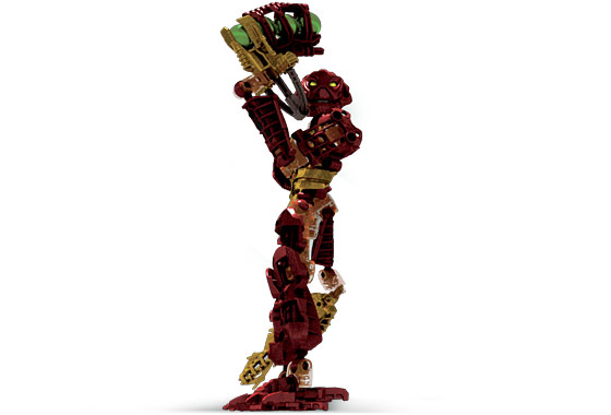
There wasn’t really anything that caught my eye, just browsing on Google and Bing, so I went to BioMediaProject in case they had some extra material I hadn’t seen before. That’s when I saw this:
A render of Jaller, in the exact same pose I have Hahli in currently. I have no clue where this render comes from, and part of me doesn’t even believe its official, but I figured this was honestly the best option I had, again not including the display case pose.
It does cheat a little bit, as a majority of official Inika renders do. The camera is below the floor looking up at him, which makes him look like he’s balancing on one foot, and his sword also seems to go below the floor, but it’s definitely more tame compared to some of the others.
I copied the pose over, but I wasn’t entirely satisfied with the results as it just put his sword out of focus too much which, given how much effort I’ve put into making these swords light up, I definitely didn’t like. So I fumbled around with the pose a bit and came up with this:
(I forgot to take an image before re-posing him, so excuse the lack of a comparison)
I’m not sure why the perspective on my camera looks so off, but I can definitely assure that it looks much better in person. But I do quite like this pose a lot better than what I had before. It’s definitely more inspired by the display case than I had realized while making it, but I think I managed to pull out the good traits while leaving some of the bad traits of that pose behind.
I’m still really happy with Hahli’s pose, and while Kongu needs a bit of tweaking, I’m also still overall happy with his. And Matoro gets the only pass to be the stoic, heroic one of the group. So that just left Nuparu, who I really wanted to overhaul, but there really isn’t much that he can do given his claws, but I really didn’t want to leave him in the basic default pose he’s always in.
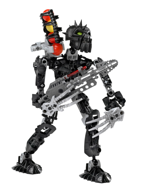
Looking him up, I wasn’t surprised to see almost every picture showcasing him two-handing (two-clawing?) his drill, so I again went to BioMediaProject to find extras, and found these two:
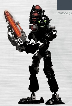
On the left is his stock photo. Every Lego set has one of these, but I’m unsure if they were ever used anywhere outside of the pages on Lego’s website that contain their instructions. But regardless, they clearly are taken by some third-party company, because a lot of them will have weird poses or even completely incorrect features (for example, Jaller’s stock photo shows him with his sword and Zamor launcher on opposite hands, and one of Thok’s photos shows him with his feet on backwards!). That being said though, sometimes that strangeness can be admiring, like in the case of Nuparu here.
Contrasting the real set photographed by people who didn’t understand it very well, is the digital render created by people who definitely had access to a style guide to follow. I’m again not sure where this render is from, or where it was used, but while it does feature Nuparu’s standard two-hand pose, there’s just something about it that makes it stick out from the rest I saw. I partially believe it’s in large part due to the way his eyes glow/shine, but I think having him be in a stance that’s a little more natural also definitely helps. It also only cheats one time, with his left arm being rotated in a way that isn’t possible with the real set.
I had a feeling that the pose on the right wouldn’t really translate well into real life, so I tried copying that first, and as I suspected, the appeal of the render comes in large part due to the way it’s stylized.
So I moved on to the stock photo pose. It definitely looked a little awkward, so I tried just messing around and seeing what I could come up with. I had a lot of trouble finding something for his open hand to do, and also finding a balance between showcasing his drill and his claws.
After a lot of trial and error, I eventually managed to come out with this:
I’m not 100% satisfied with it only because I can’t really explain the “story” of why he hit this pose. Granted, the Rule of Cool overrules this rule, but still, it’s not absolutely perfect.
I think what really makes it hard is that Nuparu suffers from the same issue the future sets from 2009 onwards would face, where his claws give him more of a realistic hand look, which can make unnatural poses look really awkward and noticeable, which isn’t a problem with the standard “hand” that the rest of the Inika have. Oh well.
Back to Business
I’ll let the Toa sit in their new poses for a while so that I can come back to them with fresh eyes and decide if I really like them all.
Now, full disclosure, the posing aspect took much longer than I thought it would, and it is now the next day from when I started printing the top case for the Arduino. This is all to say, the 3D print has finished.
I put the pieces together, and while the case looks and feels nice, the board inside is still entirely loose, which is exactly the problem I was trying to solve.
I solved this problem by attaching a piece of foam on the SPI pins on the back, and also adding the reset button that was provided with the 3D print. I also found some screws to fit on the mounting holes I added.
It’s not perfect, but it should get the job done. I also just really don’t want to reprint the case with a tiny modification.
But with that settled, I can go ahead and get more proper measurements to determine how much space I’ll need underneath. From a somewhat rough use of the micrometer, I came out to about 50 millimeters, which didn’t seem like too much. I attempted to simulate the space by using some wooden blocks that measured out at exactly 50 millimeters, and, well…
It IS a lot, way too much, in fact. Because remember, I have to cover both the foam, and the blocks. Some of that space can definitely be covered by the banner decal that will be wrapped around the display, but the paper for that is already so expensive as is. To cover ALL of this space, I would need to upsize to a massively sized paper, which would just end up making the design look awkward. This is not to mention that I would have all of that extra empty space sitting there for nothing, which makes it a complete waste.
I checked again and again, but I really don’t have the option to attach the Arduino like this, so I’ll need to reevaluate my plan.
The Tinker
I gave myself the requirement of keeping the board/case as hidden and as out of sight as possible, since it would just be lazy to slap it in the corner and call it a day. I know I can do better than that.
I managed to come up with two ideas that met this requirement. The first one I had was to put the board on top, where the Inika are, and disguise it as a stone, or something similar, that Kongu would be stepping on. His pose in the Piraka Online Animations, that I copied, seems to have him standing in such a way, which I think can definitely add to the coolness factor, give a bit of extra depth to the display overall, and help Kongu not get lost in the background.
However, it’s not a perfect solution. The first issue I ran into was figuring out how I was going to manage the cables. To this end, I had two more ideas. Either I can place them upside down and run them underneath the foam through a hole and then back up top into the Inika’s swords. Or, I could keep the board upright and incorporate some way to manage the cables in the design of the board’s disguise. I personally prefer the first method just for its simplicity.
Speaking of the disguise, that brings me to the biggest hurdle with this idea. I’m not entirely sure how I’ll create a design for this that works. Currently, I’m thinking that I can either redesign the 3D printed case for the board, or I can mess around with foam terrain. Both of these will require a lot of work and a lot of time no matter what, so that’s why I came up with a backup plan just in case.
My alternative plan is to keep the Arduino board underneath the foam base like the initial plan, but have it facing upright, and with a hole cut into the foam so that the cables can be plugged into it. This one is definitely less work overall, but it gives less ability to manipulate the cables so that they’re better hidden. I could have the cables run through the foam, but I don’t see any easy way of accomplishing that with my tools.
And just in case neither of these ideas work out, I have a third plan. Borrowing from the display case, I’d keep the Arduino board on the top of the display, and have wires running down behind a background, under the board, and then back up above into the Toa’s swords. The problem with this idea is that it would require fundamental changes to my overall design. First off, to hide the board at the top, I would want to add some sort of lid with a shield, just like the one seen in Jaller’s display, so that it’s not visible, but then that would mean the display couldn’t be viewed from above. It would also require me to add a background, again just like in Jaller’s display. And while I’m not entirely opposed to this, it will drive up costs, and I still don’t necessarily know if that’s what I want yet.
I’m still hesitant to fully dive into any option, so I want to prototype first.
Toiling Away
I chose to give a go at my second idea of putting the board underneath the base. Since the test foam I have already has some holes in it, I just borrowed one to test the idea so I wouldn’t have to worry about making another one.
As I expected though, doing it this way means the cables are very exposed. There may be a way I can blend them in, but it’s going to just be a lot of work that requires a more experienced hand, and a more organized mind, which I don’t possess either of.
So instead, I figured all of that effort would be better spent on creating a disguise.
First, I started with positioning so I could see what the final product might look like.
I’m honestly very happy with how this makes Kongu look. Quite honestly and plainly, it’s just straight awesome. I’m now certain this is the way I want to go, it’s just a matter of making it look good.
I also added some other Toa alongside Kongu, just to see if my theory that this would help him stick out was correct.
It was not, but I believe that’s due to him not actually being raised up at all. This may be a good thing, or I may end up changing it; I’ll see about it eventually.
Fun fact! – Kongu on the big screen
Wow, two fun facts in a single post. I must be spoiling you all.
While all of the Toa Inika made appearances in the first Bionicle movie (Bionicle: Mask of Light) as Matoran, some got more attention than others. Jala was the secondary protagonist, Hahli directly witnessed and chronicled Takanuva’s battle against Makuta, and both of them represented their village in the championship Kohlii match at the beginning of the film, with Huki representing Po-Koro in the match.
This left Kongu, Nuparu, and Matoro out, each of whom, as far as I know, were not seen at all in the movie. However, in the second movie Bionicle 2: Legends of Metru Nui, Kongu not only made a somewhat notable appearance, but also even had a few lines. His only scene was as the Le-Matoran working the chute system, that ran throughout Metru-Nui, being intimidated by Nidhiki and Krekka to reverse the direction of the chutes so the pair could catch the escaping Toa Metru Vakama, Matau, and Nokama.
Measurementing: The Sequel
I gave some more thought to my idea, and I was suddenly hit with a revelation. I had been worried about the wires sticking up out of the board, and while I figured I could hide them well enough in the disguise, I wasn’t sure how it would turn out.
But instead of that, I could essentially combine the two ideas I had by keeping the board above ground in a disguise, but flipping it over and making it so that the cables could go underneath the base, and then run directly to their respective Toa.
This provides two benefits. First, it of course makes hiding the cables much easier, but it also gives some use to the underside of the display, which in turn, will allow me to gather measurements a little bit easier, so I will try this design.
To get a prototype idea, I took the top part of the Arduino case, traced out the holes for the cables, and cut into the foam as best as I could while following the outlines.
It’s extremely messy, both in terms of the final outcome and the process itself. This is something I will need to fix if I plan to create the Arduino disguise out of foam. I’ll do some practice whenever I have a chance.
But, with these holes in the foam, I’m able to easily fit the cables underneath and make a separate hole for wherever they need to come back out of.
Looking at how much the cable droops, I feel that’s a good point of measurement, so I can assume that I only need room for the rest of the cables to be able to move a bit. Going off of this standard, I came out with about 15 millimeters of space; under half of the size of the wooden blocks!
To put it into a visual perspective, I found some rolls of electric tape that measured at 13 millimeters tall, so just slightly below what I want to do, and it looks much more respectable:
It still gives enough space for me to put cables underneath without them being practically glued to the foam, along with some extra leeway in case I find out I need a breadboard for whatever reason. It’ll also be much easier to design a decal strip for this amount of space.
So with that done, I must end the blog post here as I am out of time for this week. It wasn’t a lot of progress, but it was important innovations.
Coming Up Next
Cartland informed me that my materials have been purchased, but I should expect them to arrive the week after the next. This works out fine since I still have some progress to make on the foam side of things.
My plan for next week is to design a supporting beam structure to lift up the foam base. I currently have an idea of what I’m thinking of sketched out already, but I’m sure there’s something important about the design that I’m overlooking. Nonetheless, I’m confident I can finish it next week.
I also will practice more with painting and decorating the base, as the basic grey floor is too boring on its own. To this end, I’m thinking I can borrow some more techniques from Adam on YouTube, and I have some ideas already for what I think might look good.
And then, of course, I’ll need to figure out how I’m going to create this disguise for the Arduino board. I’m really, really not looking forward to this, especially with my extra foam being so limited. I know I can ask Cartland to purchase more, but again, I’m trying to keep costs generally low, again because of the upcoming Plexiglass and paper printing costs.
All of that should keep me more than busy enough to cover next week. But once I have all of those done, the only things left to do will be:
Finalize the ideas for the base paint and decorations
Get the cables attached to the Toa’s swords, and try to keep them organized
Apply both of the above on to the final foam base
Design and print the decals
Apply the Plexiglass
This definitely isn’t a fully comprehensive list, but it still shows that there’s not too much left to do. The hardest parts of this are nearly out of the way. With only 5 weeks left to go though, I definitely want to pick up the pace a bit.