Category: Boone Flume

  • Final Post!

    Hey guys, this post will be the last one regarding my project. Before I start anything else, I’m extremely grateful for the DKC allowing me to do this. The experience as a whole was something I highly recommend to anyone looking to get into science or design. It teaches you how to manage your time effectively, meet deadlines, work as part of a team, and manage a large-scale project. I know I have said it before, but the biggest takeaway for me was learning what progress in science is about. Growth is non-linear on these projects, and that is the unfortunate truth about science. There would be weeks of very stagnant growth, and then all of the sudden there would be profound progress, and that really is the beauty of one of these Fellowships is that it prepared me for that in science. Another important takeaway is there will always be something to do that will benefit the long-term well being of your project. Regardless of where the physical construction piece of the project was, there was always something I could do on my computer, or with the supporting pieces of my project. Anyways, I will be outlining the finishing touches of my project in this post.

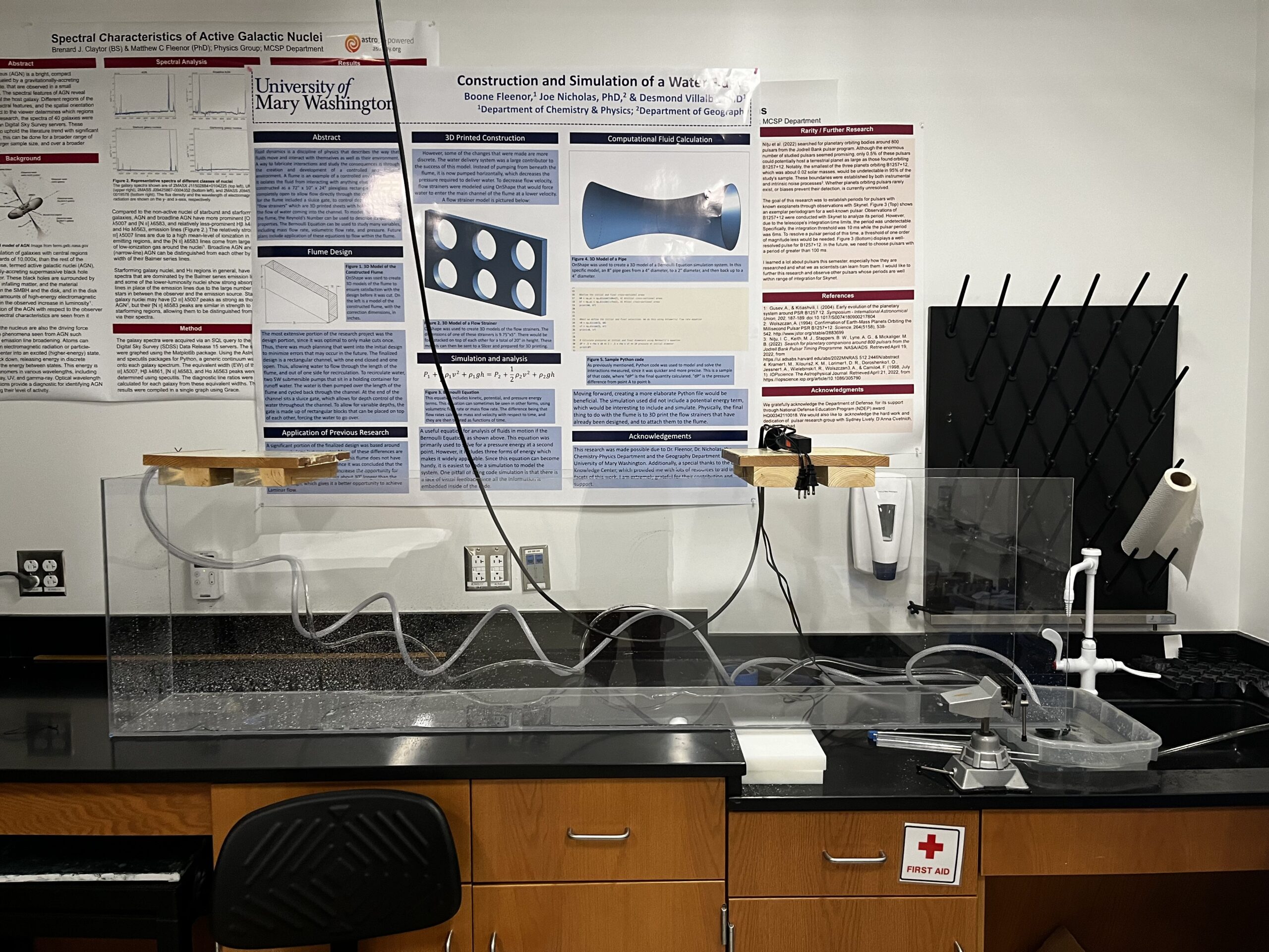
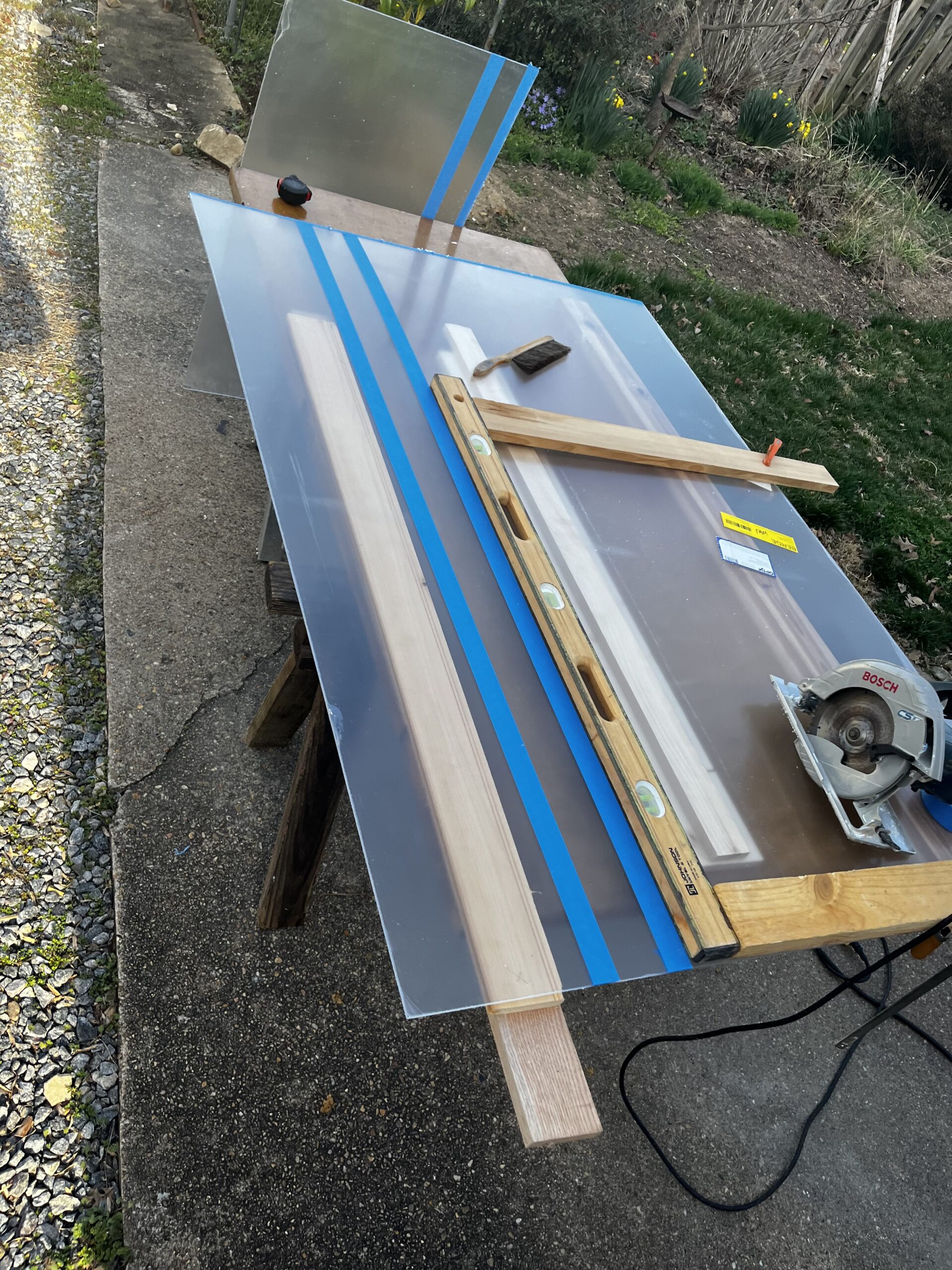
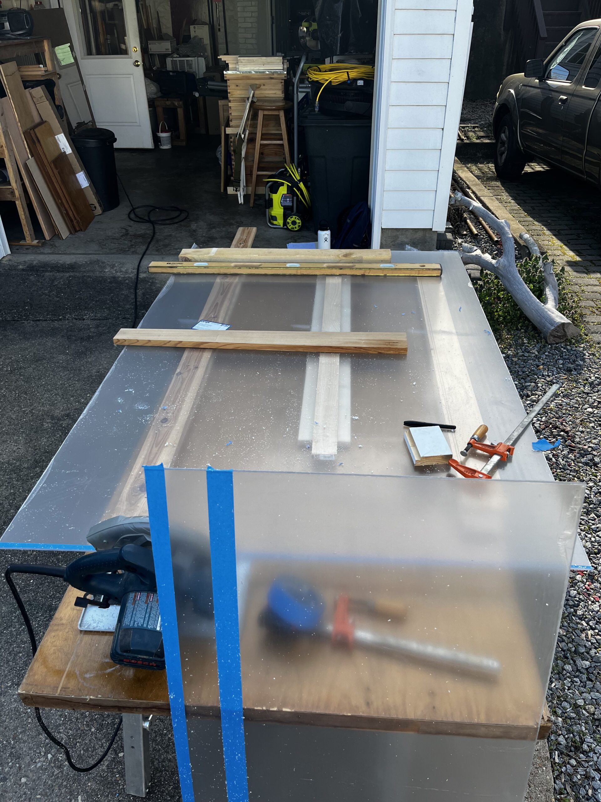
    The biggest obstacle right now is that one of our 3D printers I broken, which was an unforeseen obstacle. So, I haven’t been able to print out some of the smaller things. But, all we have left to do is create the gates that will give the flume some depth, and then we will be done! This includes the gates on the end, as well as the front. I will include some photos of the flume in its current state. In the future, Summer maybe, I will be able to create another post of the final-final project. However, the flume is finally complete. Thanks again for everyone who supported and followed me in this journey.

    a water flume sitting on a bench in a lab
    This is where the flume stands right now. The wood blocks are just to give it more stability, but will increase in practicality as the depth of the water rises in the channel.
  • Construction Update + Research Presentation

    We have officially put the flume together! Which was super cool to see and very exciting. I think that I have been working on this project for so long that it became something in my head that I never really thought was going to materialize. So I am super grateful for the DKC because they allowed me to take this project to the next level. The PVC welding was super easy and affective, and it was definitely the right thing for this project. I have been using OnShape quite a bit recently to design 3D models of some things to see how they look, and to hopefully 3D print them soon. I will attach some of those images in this post:

    This was a 3D model of the flume, with the correct dimensions. I pushed it to a drawing because I liked the way that it looked almost like a blueprint. For the other images, I left them as a 3D image.

    In a previous post I mentioned a “flow strainer,” which was a 3D printer mechanism to decrease the velocity of water in the flume. This is the 3D model for the flow strainer, and I think this makes it much easier to image.

    Research Presentation

    Later today is the UMW Research and Creativity Day. I will be presenting my individual research in unison with the Digital Knowledge Center research, since they go hand-in-hand. It will be a great time, and I’m hopeful that it will expose the DKC to many more STEM majors, since I think it is a great resource for research-oriented minds. Below, I will upload an image of my Poster, so that even if you’re not there, you can give it a look!

  • Big update!

    I am happy to say that I was able to put the flume together today! The epoxy weld has a 72 hour curing time, so it will be a little bit until we are able to put water into it. However, it was super exciting to finally put it together and see it in all of its glory. I am going to include some images of the flume:

    We crafted some supports with 2x4s and some spare wood to hold the walls of the flume in place, as well to add support so that I was able to weld the pieces to the bottom plate.

    I was super pleased with the way that the back plate fit in between the two walls, and it seems like it’s going to be a perfect fit. This was relieving because working with water can be super difficult. If there are any gaps in the welds we will have to go back over them with an acrylic filler to prevent leaks.

  • Flume Inspiration!

    Entering college, I was pretty unexperienced in the academic realm of physics and engineering. It was hard to know what I liked and what was out there without being familiar with a lot of the jargon and concepts of Physics. Most of my experience coming into college was from working on cars, but I had never taken a calculus-based physics or engineering course. However, I did know that I wanted to work on moving things, and that physics classes were where I needed to be in order to gain the knowledge to do so. The second semester of my freshman year, I got invited to join the Geography Department on a project to update and design a new flume for them, as their previous design was problematic and leaky. On the physics side, this project fell into the realm of “Fluid Dynamics,” which is the study of fluids, and the way they move through and around objects.

    Fluid Dynamics as a sector of physics has more applications than someone might imagine, since air is treated as a fluid in physics. So, the sector of Fluid Dynamics covers everything from water interacting with a submarine to a rocket moving through the atmosphere. Additionally, the project involved designing and building a flume, not just studying them, so it had a lot of potential as an engineering project. When I was reached out to about joining the project, I had no idea how to build a flume, and had minimal knowledge of what a flume was or how it was used. So, naturally, I went straight to YouTube to see what I could find, which would give me my first major lesson of the project.

    I found a channel called Fluids Explained, where a professor in the UK had built a home flume as a Quarantine project. Although our design was different, we used some of his techniques to try and improve the previous design. When we came to terms with building a completely new flume with a different design, I immediately reached out to the owner of the channel. Being an educator, he was very responsive and helpful with our design, despite me being initially nervous about reaching out. This was an important lesson because, for the most part, creators want to see other creators succeed, and when they do something that they think was cool or fun, they want to share that with other people. So, being curious and asking lots of questions has been something I have been working on doing, and I would encourage everyone to ask as many questions as they want.

    • Fluids Explained channel: https://www.youtube.com/@fluidsexplained1901
    • Reference video: https://www.youtube.com/watch?v=sppaBqpIT-w&t=213s
  • CUT DAY!

    Yesterday afternoon, I was finally able to cut out the pieces of my flume, and prepare for assembly. It was slightly surreal for me to finally see these plans come to fruition, as this has been a work in progress for a while now. I will share some pictures in this blog post, as well as talk about the strategy and key aspects of the cut and design.

    Figure 1. An image of the strategy imposed to cut the longer pieces of the flume. This particular cut was for the bottom of the flume.

    When making these cuts, precision was always the key. Since we are trying to hold in water, they have to fit together perfectly. Thus, we also decided that it was best to cut all the pieces about 1/16th bigger, and to sand them down later. To ensure precision, we used the machined side of the plexiglass for the two longest cuts, which were the side walls. The reasoning behind this being that machined sides will be laser-cut, which guarantees exact measurements and smooth edges. Since the side walls will have the largest contact surface area, it made the most sense for those to be the pieces with the machines sides.

    Since we were dealing with a large piece of plexiglass, we had to use a handsaw over a bench saw. This was unfortunate, since it takes much more caution to make a straight, precise cut with a handsaw. The model we came up with was to have a straight edge that was clamped down right against the cut, so that the saw could essentially lean up right against it. This took fatigue and human error out of the picture, since the saw would not veer when I got tired. Also, it gave a good line to cut against, which meant I didn’t have to guess on if I was cutting straight or not. The masking tape was put over the cut, so that the plexiglass wouldn’t get marred by the saw.

    Figure 2. Shows the first cut we made, which was cutting the extra plexiglass off of the end to get the desired length.

    The smallest, and most accurate, cut was the back plate, since it had three points of contact. It was a 9.5″x19″ rectangle that fits up to the back of the flume. To cut this, we used the remaining 24″x46″ rectangle of plexiglass. The bench saw was used to ensure accuracy and precision on the cut, and I think it turned out pretty close. The official cut was 9-9/16th, so that we can a snugger fit. The next step on the progress to assemble the flume, which will be done using a plastic-welding solvent. The next post will address the idea behind plastic welding, and the inspiration behind the project!

  • It’s a date!!

    We finally have a date to cut the plexiglass for the flume! The design that we have decided on is 72″ long, and 10″ wide. One of the unique things about the opportunity the DKC has given me, is that I’m able to be present for all of the steps of the building process. Usually, there will be different people at every step, from purchasing, to designing, to building, with minimal communication between branches. However, the DKC allows me to be involved at every step, which is rare and valuable because it gives me an appreciation of the process and gives me an opportunity to practice effective communication so that things go as smoothly as possible. For example, the actual width of the channel is going to be 9.5″ since the thickness of the plexiglass is 1/4″ thick, so when making the back panel of the flume we have to take into account that we will lose half an inch. Engineering complexities like such are often missed at one of the steps, and can create a frustrating time for one of the branches. Being able to see this at a small scale gives me practice in catching things like that, so that they won’t be missed in the future.

    Additionally, instead of using a glue or epoxy sealer to attach the pieces of the flume, I’m going to use a technique called solvent welding- a methylene chloride. Essentially, it melts the pieces of plexiglass together, and create a chemical bond between the panels. This will increase the bond strength, making the flume less susceptible to bowing and leaking. This won’t require much more work, but it is something new that will undoubtedly require some practice. In the long run, it will be an improvement, since leaking and bowing was an issue that we suffered from last time.

  • What’s a Flume?

    • Redesigning the inlet box to decrease the water’s turbulence as it enters the main channel of the flume
    • 3D printing two gates at either end of the main channel to give me control over the depth the water will reach in the main channel
    • Make it wider and longer, which will increase pressure and(hopefully) decrease the pressure of the water through the main channel