Author: Stephen

  • Final Statements: 3D Molecular Representations

    I first wanted to say thanks to those who have taken time to read the blog, and I hope you learned a a thing or two. This will be my last 3D molecular representations blog post and in it I will go over some of my final thoughts and show off all that I have learned.

    Brief Overview of Accomplishments…

    The CAD side of things…

    Three months ago, I started this project by learning how to use CAD software, Fusion360, to edit STL files of 3D molecular structures that were provided by the Protein Data Bank (PDB). Through this time, I learned how to use many of the more basic tools in Fusion360 such as sketch, extrude, fillet, chamfer, split face, combine, inspect, combine mesh, tesselate, and plane cut. These tools were all I needed to make the necessary edits in creating 3D molecular models. I have a more in-depth explanation for most of these tools linked so check them out if you are interested.

    The 3D-Printing side of things…

    The 3D-printing side of things was a more complicated matter as there seemed to be a sort of “guaranteed chance of error” with the MMU 3D-Printer. In the beginning I was making no progress because the “Wipe Tower” would not be enabled if a particular extruder was set to only be utilized for supports. After figuring out how to work around this issue another problem arose with the soluble filament. The problem here was that the PVA filament I used would constantly clog and sometimes caused a glitch where the MMU would load and unload the filament endlessly. The work around for this was simply using a different soluble filament called BVOH filament. Even with all this there were still issues that I ultimately could not completely avoid such as clogging, simple errors, and filament expiring or going bad from too much exposure to moisture. However, I did find using a filament drier was very useful in keeping filaments in good condition for longer. That idea was from Shannon and Cartland so thanks for that one!

    Final Model Montage and Final Thoughts…

    Here is a picture of the new and improved BCR-ABL model without all the printing errors from before. Now, I want mention that before I talked about “oh you can show different subunits using different colors.” I just want to say I thought using two colors here would look cool and I wanted to figure out the MMU printer and it does not represent multiple subunits in this case. Also, thanks to Dr. Agrawal for choosing these colors (they look like a gender reveal but otherwise its nice).

    Full view of assembled BCRABL model.

    Altogether

    Full view of unassembled BCRABL model.

    Apart

    Video of the assembly (not including the simulated imatinib or ATP).

    Final Thoughts…

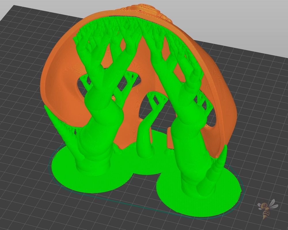
    I hadn’t mentioned it yet but in order to avoid the “drooping” of the filament for this print. I changed the infill from 20% to 30% and changed the orientation in which the model is printed. An example is shown below.

    Image of model orientation on the first attempt.

    Before

    Image of model orientation on the second attempt.

    After

    Once again thanks for tuning in. I had a great time with this project, and I think I learned a good bit. I think there is much more that can be done with this concept and there are plenty examples of “model molecules” that can be printed to be used as a teaching tool. I may continue this project in my own time before presenting to the Research and Creativity Day symposium in the Spring because there was more that I wished to do. My big idea for this project was to make a series of models that can explain mechanism of molecules such as hemoglobin, but I ran out of time. For example, imagine a series of models that starts with a model of hemoglobin similar to what I had done in this project but with a highlighted section (section printed in a different filament). Then next to this model was another model that is the same color as the highlighted section (for example the porphyrin rings) which shows how the interactions of the ring to hemoglobin allows interactions with oxygen or CO2. I had an idea to make a wider model stand that can occupy two models to be displayed which would facilitate this idea. Anyways, good luck to those who wish to replicate this process.

    It's over... It's finally over.
  • BCR-ABL Part 2: 3D Molecular Representations

    Tony Stark arms spread 
"It's done"

    In my last post I went over how I edited my BCR-ABL model in Fusion360 but here I will discuss the printing process. I have now returned to using the multi-extruder with some new tools and settings which I will discuss later on. Spoiler alert, IT WORKED!

    Image of the BCR-ABL model completed in CAD.

    New Filament…

    One of the things that I was unable to do at the start of this project was use soluble filament for support structures. I had originally used a PVA filament from Polymaker which has a printing temperature of 215-225°C and costed around 60$ for a 0.75kg wheel. We have since upgraded to a BVOH filament from Verbatim which has a printing temperature of 210 ± 10°C and costed upwards of 140$ for a 500g wheel. Overall, BVOH filament is far superior in all regards as it dissolves in water faster, it does not absorb humidity as fast and therefore can last longer, the possibilities of “stringiness” during printing is lower, and the extrusion can be more continuous. Now yes, it is also far more expensive, but I was completely unable to get anything to print with PVA and I made progress with BVOH. I believe this filament was much better than PVA because the printing temperature of BVOH is very similar to that of PLA meaning temperatures remain relatively constant throughout the print. This reduces the chance of “goopy” filament extrusion due to temperatures being too high and reduces the chance of filament solidification (clogging) from temperatures being too low.

    Image of the BVOH box showing company.

    Filament Dryer…

    As I previously mentioned, BVOH filament does not absorb moisture as well as PVA, however soluble filaments across the board are more susceptible to going bad from sitting out compared to other filament types. This is most apparent during prints where the filaments can be sitting in open air for hours at a time. To resolve this issue, we purchased a COMGROW Filament dryer. This dryer can hold two wheels of filament at a time which can be left running during print times. An image is posted below.

    Image of the soluble support BVOH filament sitting in the filament dryer during a print.

    Print Settings…

    Now these print settings have not changed much, and the biggest difference was made by using a different filament with a filament dryer.

    Image of Print Settings.

    The main changes that I wish to highlight are all under “Options for support material and raft.”

    • Style: Organic (read my last post for more details on organic supports)
    • Top Contact Z distance: 0 (this is what is recommended for soluble support printing)
    • Top Interface layer: 1 (this is just to further improve upon removal of supports)
    • Interface pattern: concentric (this is what is recommended for soluble support printing)
    Image of PLA Filament Settings.

    These are the temperatures I had set for the PLA extruders. (note: bed temperature was later set to 70°C)

    Image of BVOH Print Settings.

    These are the temperatures I had set for the BVOH extruder. (note: bed temperature was later set to 70°C)

    BCR-ABL Printed…

    This will be a small montage of the print including a video of the soluble supports submerged in water. See you one last time next week!

    Shows full model assembled on the stand.

    Shows off the model fully connected together with Imatinib (red) in the substrate binding pocket.

    Shows each individual piece of the print.
    Image showing off model warping.

    This print was a major success however there were some issues. As you can see in the second image one of the pegs broke while I was trying to join the pieces. This issue can be solved by increasing the infill to strengthen the pegs. In the third image you can see apparent warping to the pink half. This issue is something that I don’t understand yet. I assume because the model was printed peg side down there was drooping of the model despite using supports. In the final model I hope to avoid these issues by increasing infill, printing the model flipped so the peg side is up allowing for a stronger base to avoid drooping, and increasing the bed temperatures to allow the filament to stick better.

  • BCR-ABL: 3D Molecular Representations

    Sneak peek secret... revealed as the BCR-ABL with Imatinib in the substrate binding domain.

    Hey everyone, this will be a short post today with another planned to go live by the end of the week. I left off giving a sneak peek into the next modeling project I planned with BCR-ABL. This post will go over the process I went through to edit this structure in Fusion360.

    Image showing the website where STL files were collected.

    Firstly, the STL files for BCR-ABL and Gleevec (Imatinib) were obtained from the link provided. Chronic myeloid leukemia (CML) is a cancer of white blood cells. In CML, white blood cells divide uncontrollably due to an overactive tyrosine kinase protein called BCR-ABL, which results from a chromosomal translocation. This chromosomal translocation creates what is known as the “Philadelphia chromosome.” Research into CML treatments has consisted of understanding the mechanisms of BCR-ABL. Since BCR-ABL is classified as a kinase enzyme there is an interaction with ATP. Researchers were able to understand that inhibition of ATP to BCR-ABL resulted in deactivation. This led to the production of Imatinib, an inhibitory drug that binds to BCR-ABL competitively with ATP.

    Editing BCR-ABL in Fusion360

    Since the mechanism of Imatinib binding with BCR-ABL involves a conformational change that locks the molecule inside BCR-ABL, I had to do a slightly different design for modeling the substrate binding. In this new design the model of BCR-ABL is split down the middle allowing for the model of Imatinib to be inserted in the substrate binding zone before closing the BCR-ABL model. The same process can be done with ATP to show the similar binding process.

    Image showing how Plane Cut function is used.

    This was completed by using the “Plane Cut” function. This can be found under the “Mesh” tab, subsection “Modify.” When using this command ensure that “Type” is set to split body and “Filly Type” is set to uniform.

    Image showing two cylinders with dimensions.

    Two cylindrical tubes were created at around a 50mm diameter (important for later) and positioned in areas that allow them to act as pegs when printed.

    Image showing hole cut out with dimensions.

    These cylindrical tubes underwent the “Tessellate” function (found in the “Mesh” tab, subsection “Create”) and subsequently the “Combine, cut” function (found in the “Mesh” tab, subsection “Modify”) was used with each half of the BCR-ABL model creating a hole for the peg (one for each half).

    Image showing peg extension with dimensions

    A new set of cylinders was created using the same process as before but at around a 48mm diameter. The diameter was reduced slightly as in the last print using pegs, I found it was too difficult to pull the model apart.

    Image showing model stand with name tagged.

    I decided to use the same stand that I created before since it looked quite nice, and I had no issues with it. The procedure for completing this process is outlined in one of my previous posts if you are interested.

    Image of entire model together on the stand.
    Image of the model separated into pieces.

    This is an image of the final product. In my next post, which will go live either tonight or tomorrow tonight, I will go over the printing process for this model. The next post after that is my last post in this series 🙁 which will go over my final project in its entirety.

  • Significant Progress: 3D Molecular Representations

    Hands up, crying emoji. Just cause I relate...

    Where we left off…

    Hello again to those reading the blog. It has been a complete struggle with the multi extruder going from issues galore to straight up malfunctioning. Point being I have made basically no progress with the multi extruder, and I plan to try my best to get something over the next few weeks. Regardless, to keep moving forward I have been mostly working with CAD to figure out a good way to interconnect multi-subunit structures. I have already printed one of the designs and I feel pretty good about how it came out.

    First off check out those organic supports… even if they didn’t improve the efficiency of printing, I would use them, I mean look at how cool they look.

    There are many parameters that have changed since when I first started printing these structures and I think for those who are trying to replicate this process it would be good to go over each change separately. Furthermore, there are many steps to this process that I never touched on and those will also be listed here as well.

    Where and how to find STL files of 3D molecular structures…

    Where: I have always taken STL files from a website called the Protein Data Bank (rcsb.org)

    Finding STL Files:

    • To obtain a molecular structure STL file you must first assign a 3D representation to the molecule of choice. This can be done after moving to the “Explore in 3D” window.
    Image showing what you would see during this first step.
    • When you are able to view your desired structure in 3D, we are then able to edit the 3D representation of the molecule. This is done under the “Add Representation” setting which is under “Components”
      • Note: Ensure you remove all of the previous representation that were assigned to the model prior to exporting the STL file. If this step is skipped, the compounding representations cause issues during printing.
      • Note: I have always used the “Gaussian Surface” or “Molecular Surface” representation for my prints, but I did find the “Gaussian Surface” representation prints more cleanly (Even though I think Molecular Surface looks way better 🙁 )
    Image showing what you would see during this second step.
    Image to disclaim the note below.

    Note: Noticed how there are both “Cartoon” and “Gaussian Surface” representations present for the polymer. If you look closely there are sections where the cartoon representation (ball and stick) is sticking out of the Gaussian surface.

    • After the representation is assigned to your Polymer (molecule) it may be in your best interest to delete the “water molecules” and ligands (unless you wish to print these as well in which case you will have to edit the ligands representation in the same fashion as stated in the last step).
    Image showing where to remove the water molecules.
    • Finally scroll down to “Export Geometry” as an “STL file.”
    Image showing where to export the STL file.
    What 3D-Printing Software do I use and what settings have I changed from default…

    Software: At my university we use Prusa printers and have therefore opted to use the Prusa software for 3D-printing. Keep in mind that any 3D-printing software can be used to have a similar effect, however I cannot promise the information I have provided transfers.

    Changes to settings: (At this point 11/11/24)

    • One of the main changes I made to my printer settings was the use of “Organic” supports. This was a fairly recent development for me however for the particular models I am printing it makes a huge difference.
      • Note: Regardless of how nice the organic supports are, soluble supports are still vastly superior.
    • Making minor adjustments to extruder/heat bed temperatures (increasing if clogging is an issue or decreasing if the print quality seems reduced; i.e drooping).
    • Other support settings that I have changed with variable rates of success include: reduction in “Top Interface Layers,” changing the support “Pattern,” and changing the support “Interface Pattern.”

    I have gone into more detail concerning most of these changes on other blog posts so check there if you are interested.

    The New and Improved?…

    Now that we got that out of the way I can discuss the progress I made over the last couple of weeks. I have been working with a molecule called hemoglobin during my last few prints and this is not without reason. Hemoglobin is the oxygen carrying molecule that resides in our blood which is composed of 4 subunits (typically 2 alpha and 2 beta subunits however there are some forms that are 2 alpha and 2 gamma). Of these 4 subunits each contains what is referred to as a protoporphyrin ring which is a complex ring structure that contains an iron center which is responsible for binding molecules like oxygen, carbon monoxide, and other molecules like 2,3-BPG. The 4 subunits of hemoglobin are folded into a quaternary structure that is formed through multiple hydrogen bonds and disulfide bridges. I know that sounds like a bunch of nonsense, but all of these characteristics of hemoglobin can be represented in a single 3D molecular representation. The bonding between subunits will be represented with pegs in some precise locations (not all as that would be crazy) and the distinct protoporphyrin rings can be shown using a disk that slides in and out of the model. That was a long-winded explanation but here is the final product…

    Image showing off model and stand separated.
    Image showing model and stand connected.
    Image of model and stand connected (different POV).
    Image of just the model to highlight the disks.

    Notice the disks. These are the disks that represent the protoporphyrin ring systems. There are only two just because I just wanted to test an idea. Also, later on these will be a different color to the base model.

    Image showing the model with the disks removed.

    What’s Next…

    These next few weeks are exciting as we have received a shipment of new PVA filament for soluble supports. The last batch seemed to have gone bad as large segments of the filament absorbed too much moisture. We also purchased a 3D filament dryer which I would highly recommend to anyone that plans to take on larger 3D printing projects.

    Furthermore, I plan on switching to a new design a new molecule called BCR-ABL. Now if you want to explore this before my next post GO FOR IT. I will be providing a semi-in-depth explanation of what this protein is, why is it a good protein for 3D modeling, and how it related to chronic myeloid leukemia (CML) in my next post. Oooooo, sneak peek I know… exciting.

    Seek peek secret...
  • Shifting Goals: 3D Molecular Representations

    Hello everyone, this is my fourth blog post that outlines updates on my 3D molecular representations project. This one might be shorter than previous posts, but there are a few things that I need to address. Firstly, the soluble support that I was using previously (Polydissolve S1 from Polymaker, PVA Filament) went bad and I am currently waiting for the new filament to come in. I was not aware that I needed to keep this filament in a very dry environment, and it seems the filament absorbed too much moisture and became extremely flimsy. This seems to be the reason why there were so many MMU loading errors and misprints as when the filament tries to move through the MMU tubing and into the MMU extruder it kept getting jammed. Secondly, I have tried to transition into using a combination of PETG/PLA filaments instead of the PLA/PVA filaments however I am still having issues with printing with multiple filaments.

    Side note: That weird white looking stuff on the base is spray glue from when I attempted to save this print with the only glue that I had near me… 🙁

    Stand Issue… And SOLUTION!

    I was satisfied with the old stand design, however, when I attempted to remove the supports, the peg snapped, and I decided to redesign the stand. The issue seemed to be a lack of support to the base of the peg which made it very unstable. Also, remember in a previous post I talked about added a simple design in the stand that displays the molecular name… well I did it and it turned out quite nicely. The new design is shown below:

    Also, this grey filament is PETG just like with the blue filament shown previously, and I must say it looks so much better than PLA. But just like with PLA, I still have some “support scarring” on the bottom of the model as shown below.

    Different Print Settings…

    I decided to make an effort to supplement the soluble support and did some digging into the advanced print settings on Prusa and found a few interesting things. Firstly, the default print settings have the interface pattern set to one that is most ideal for soluble supports and there is another setting that is recommended when soluble supports are not used.

    Under the “Print Settings” tab in Prusa, there is the “Rectilinear” option, which is ideal for non-soluble supports while the “Concentric” option is for soluble supports.

    Secondly, there is an option to make the interface layer between the supports and model much thinner and therefore easier to remove.

    Thirdly, there are support pattern options labeled “Grid,” “Snug,” and “Organic” which essentially changes the design of the support.

    • Grid: The default style that prioritizes sturdiness over all else and can result in supports that are extremely difficult to remove.
    • Snug: Similar to Grid except the supports conform to the shape of overhangs and results in reducing filament waste, easier to remove supports, and reduced stability in some parts of the print.
    • Organic: Think of tree branches that wrap around the model to give support instead of scaffolding like with Grid and Snug. This method is fast and cheap to print however it is a poor option for some models and often excels when used to print something like a mini figure.

    In the past I have always used “Grid” as that is what is set at default however, I tried using “Snug” for the redesign stand, and I personally think it helped with support removal. I have yet to use Organic however, I will be trying that sometime this week. Below is an image of the “Organic” support style that I found on google since it can be hard to visualized.

    Next Steps…

    My next objective is to take a molecular structure like hemoglobin and separate it into its 4 subunits (2 alpha and 2 beta subunits) for multiple reasons:

    1. This will allow for the models to be disassembled to be viewed as not just one structure but as multiple structures that come together and form one structure.
    2. This will improve print quality because molecular models are very complex and the autogenerated supports within the model can get stuck. This wouldn’t be an issue if I could figure out soluble support printing, but you know how that goes.
    3. This will allow for larger models to be printed as the separate parts can be arranged on the heat bed instead of altogether. This can further improve print quality as well because the model is being printed in a more horizontal fashion instead of vertically.
    4. This will allow pegs to be created in locations of known cysteine-cysteine disulfide bridges to further illustrate how these amazing molecules are created and folded. This is not just for looks either as the pegs will allow the model to be put together and displayed on the stand.

    That’s all for now. See you next week!

  • Third Steps: 3D Molecular Representations

    Image of the hemoglobin molecule described in a previous blog post.

    Good evening, everyone, I am back once again with another update on my “3D Molecular Representations” project. Since my last post I have been working in CAD and trying my hardest to get this MMU printer to work. In this blog post I will mostly be talking about what I have been up to in CAD as I did not make much progress on fixing the printer issues. Also, the image above shows the print that was running in my last blog post. I personally think the white appears to have a pinkish shade to it as a result of red and white filament being dispensed through the same extruder. I would have expected the wipe tower would completely negate this effect but it that does not seem to be the case.

    Designing a Molecule Stand!

    Since my goal is to print models of molecular structures, I thought I might want to have a nice figure stand. This was a simple task and I’m pretty proud with how it looks.

    Image of the simple base and peg design.

    How It’s Made…

    Image of the first step which is a drawing of a rectangle and triangle.

    First start with a thin rectangle with a triangular top using the sketch tool.

    Image showing how the extrude function is used.

    Then using the extrude tool, extend both shapes symmetrically to the distance that you desire.

    Image showing placement of next triangle.

    Then flip your object 90 degrees and use the sketch tool to draw another triangle.

    Image showing how to extrude using special tools to create the pyramid shape.

    Then extend the new shape but make sure you change “cut” to “intersect” in order to create the pyramid like shape.

    Image showing how fillets are made.

    Then to create fillets, select each of the corner edges and use the fillet tool (or press f) to create fillets.

    Image showing how Chamfers are made.

    To add Chamfers, select each of the top edges and press the modify tab to select “chamfer.”

    Image of the final baseplate.

    I was also thinking it might be super simple to make a little “design” in the base of the stand that displays the name of the figure. I think next for the next iteration I’ll make an effort to include this detail.


    Making Pegs for the Stand!

    The Issue…

    My goal in this step is to make a peg attached to the stand which matches up perfectly to a hole in the model itself. This step took me a bit of time since I was not familiar with mesh objects vs model objects. Model objects are basic structures that can be easily made in CAD with a sketch and extrude tool, whereas mesh objects are complex structures constructed by connecting varied sizes of triangles to order to replicate the shape a desired object. When I tried to use both mesh and model objects in Fusion360, the two would not interact with each other and could not act as a single piece but would instead operate as two separate entities. When working with STL files (the files used for 3D printing) it will almost always contain mesh objects.

    The Solution…

    Now on the surface this is not an issue since the stand and the peg are to be printed separately. However, in order to make a peg hole in the model the mesh and model objects must be able to interact with each other. A model object, in this case a tube, is used to delete a “tube shaped” section of the mesh object to replicate a peg hole. Shown below are a series of images that outline how this is done.

    Image showing how the cylinder can be made.

    First upload the STL file of choice and then create a circle using the sketch tool and extend it to the desired length. The diameter of the circle dictates the size of the peg hole, and the length will dictate how deep the peg hole will be.

    Image showing placement of cylinder.

    Drag the cylinder into the STL model and position it in the location of the peg hole.

    Image showing how to use tessellate.

    Use the tessellate function on the cylinder.

    Image showing where the combine tool is.

    Use the combine tool on the cylinder and the STL model ensuring to select the settings shown below.

    Image showing how to use the combine tool.

    Ensure the “target body” is the STL object and the “tool body” is the cylinder. Select the cut option and press ok.

    Image showing the STL after being cut.

    The Result…

    Image of STL with stand design.

    The BIG BAD…

    The Great Multi-Extruder Printing Problem

    In my last blog post I discussed a big issue I have been running into with multi-extruder printing which is… well working with multiple extruders. I have found that using any filament other than PLA in the MMU results in clogging, jamming, misprints, filament oozing, and print crashes. I seriously cannot think of a solution to this issue and will be trying my best to address the issue next time.

    Sneak Peak

    For the sake of progress, I decided use PETG filament with PLA filament instead of PVA/PLA. This is because the two filaments are heated at different temperatures and would therefore cool at different times, causing the bond between them to be weaker.

    -PLA recommends a nozzle temperature of around 215°C and a heat-bed temperature of 60°C.

    -PETG recommends a nozzle temperature of around 250°C and a heat-bed temperature of 70-80°C.

    Now after all that good idea talk… ruined because once again the MMU struggled to dispense two different forms of filament without clogging and canceling the print. Instead, I started a print using only PETG using the non-MMU printer just to test the fit of the peg in the hole. My guess is the hole on the model needs to be just slightly wider in diameter to the peg and will also require a deeper hole. Regardless, see you next time!

  • Second Steps: 3D Molecular Representations

    Generic picture of a molecular model in CAD software.

    3D Printing

    Hello everyone! Its been a little too long since my first post but I am back and with a lovely mess of problems. Over the last few weeks, I have been looking into how to use a 3D printer. More specifically, I am trying to learn how to use a multi-extruder printer. The two major benefits of a multi extruder printer are utilizing multiple colors for a single print and utilizing soluble supports. The image below shows a 3D print that uses PLA filament as structural support. Specifically in rainbow print of the protein “Seipin” you can see the rough surface where the structural supports were pulled. Let me just say it is not fun trying to pick these models apart without breaking something along with it.

    Sepin Protein 3D Print (rainbow colored)
    tRNA 3D print (red)

    The idea behind using soluble supports is that simply submerging the model in water after printing dissolves supports, leaving just the model behind. The specific filament I am going to be using is Polydissolve S1 from Polymaker which is a PVA filament that is soluble in water and compatible with PLA filament as well.

    The Issue…

    I am currently unable to print using soluble filament at all. This issue has presented itself in many forms. I’ll start with the simplest mistakes and move to the mistakes that are currently unsolved.

    The image below is not a soluble filament print, but it does show THE ISSUE… with non-soluble support prints.

    Image of a non-scientifically accurate Bacteriophage that broke after printing.

    The Simplest: The Wipe Tower

    If you are familiar with multi-extruder 3D printing, there is a function called the “Wipe Tower.” The Wipe Tower is a structure that is printed in association to your model in order to allow for smooth transitions between the different color/type of filament. An example of what I mean is shown in the video below.

    The issue is PrusaSlicer, the software I use, does not “allow” soluble material to be printed with a wipe tower. This is not true and can be bypassed by following these steps:

    Print Settings (Top Tab) –>Support Material (Left Side Tab) –> Top Contact Z Distance set to “0 (soluble)”

    This allows for the wipe tower to be enabled in the “Multiple Extruders” side tab by checking the box. Subsequently the options “support material/raft/skirt extruder” and “support material/raft interface extruder” can be set to the extruder of your choice containing the soluble material (Mine was 2 but it does not matter as long as it is the same as the extruder the material is loaded in).

    Picture showing where to change the Z-distance.
    Picture showing how to assign extruders to supports only.

    The Annoying but Simple: Loading/Unloading Errors

    A very frustrating, but simple, issue I run into is the loading and unloading errors that can sometimes occur multiple times in a single print. My current guess into why this is happening so much is due to PVA material being much softer than PLA and the material does not guide as nicely as the PLA. I think this because I only have consistent errors when trying the PVA material and almost never have the issue using only PLA material. If you are reading and have a better suggestion for a different brand of PVA filament let me know!!

    Also, I am sorry I forgot to take a video of this event but I’m sure it’ll happen again so look forward to that.

    The Most Complex: INFINITE LOADING..

    The biggest, and most frustrating, issue is after everything is set up and the print is started. During this time the MMU (Multi-Material Unit) would endlessly load and unload the filament. Occasionally I would have issue with the 3D printer just going to the corner of the baseplate and unloading filament endlessly which is not good. This leads me to believe this is a program/machine error and not due to the PVA material. There are many different ways to approach this problem and based on my initial research on Reddit, some others found a similar issue and it was a hardware problem. After ensuring there are no clogs or any too loose/tight screws we can ensure sensors are working properly. The filament sensor may be my issue here however I have yet to check.

    Image of a labeled MMU Prusa Printer filament module. Includes filament sensor label.

    Again, I forgot to video this issue but trust me it’ll happen again so stay tuned.

    Moving Forwards: Multi-Color Print

    Instead of never using this multi-extruder 3D printer due to the issues with soluble support I decided to just print with multiple colors of PLA material. To show off the multi-color print best I decided to print a representation of Hemoglobin from the protein database (code: 3PEL). Strangely enough without any troubleshooting this print test started immediately without any issues at all. As much as I wish I could show the final product right away at the time of writing this it has yet to be completed (It takes 13 hours for a 2in x 2in model).

    Image of the Hemoglobin model including structural supports and the wipe tower.
    The hemoglobin model without structural supports or wipe tower. Red and orange highlight different subunits.

    Next Steps: More Work in 3D Printing

    The plan for my next blog post will be to move past the issues I ran into over the last few weeks and actually get even the simplest model printed. If that does not go to plan, then I might start designing a mini-final project. My vision for this includes a model that can be stuck together with pegs that were added using AutoDesk Fusion.

  • First Steps: 3D Molecular Representations

    Good morning everyone, this is my first of many posts in which I will be learning how to utilize CAD software in order to edit 3D molecular structures for 3D-printing. My first step was to find a good CAD software that was both cheap (or free) and had enough processing power to edit extremely complex protein structures. After doing some research and speaking with my father I was able to find the software called Autodesk Fusion, which excels in 3D-pritnting related CAD work. Also, Autodesk Fusion is completely free for college students and if it wasn’t it would be like 85$/month which is crazy. Regardless, instead of jumping straight to the end goal I decided it would be good to spend my first couple of hours working with the built in introductory files which help new users to familiarize themselves with the program.

    Also, a quick note, working with complex CAD files requires a pretty substantial computer (a good GPU) and I will be doing most of my work with a desktop gaming PC (GTX 2070).

    After exploring the introductory files, I found that I still had no idea what was going on and decided to consult YouTube where I found a series of videos from a channel called “The Fusion Essentials” (links below). I basically watched each of these videos and made a few designs (shown below). I think this was a perfect practice exercise because creating the dowel of the toolbox is going to be a similar process to making pegs for my models.

    Note: I haven’t made it to part 4 of the video series yet..
    (156) Getting Started with Fusion 360 Part 1 – BEGINNERS START HERE! – YouTube
    Getting Started with Fusion 360 Part 3 – Modeling with SOLID TOOLS! (youtube.com)
    Getting Started with Fusion 360 Part 4 – Modeling Tools, Cutting Holes, and Removing Material! (youtube.com)

    I was a few hours into doing this post and realized that this software needs to support the .STL files created by PDB (Protein Data Base) where I will be obtaining most of the molecular structures. Good thing Autodesk Fusion supports these file types as I would have had to restart and choose another program.

    Well, that’s that for this week. UMW just bought a multi-extruder printer over the summer so next time I hope to include a picture of a test print using soluble support material. Also, should I make a google doc showing off some of the key skills I learn in Autodesk Fusion? Did I blog properly? Also, I’m starting to really get a good idea of what my end project will look like and wow I think it’ll come out good.