This is it, the final week. It’s been a long time coming, so let’s finish up with a bang. I’m really glad I finally get to use this title; I’ve been super excited for it.
Banners and Stickers
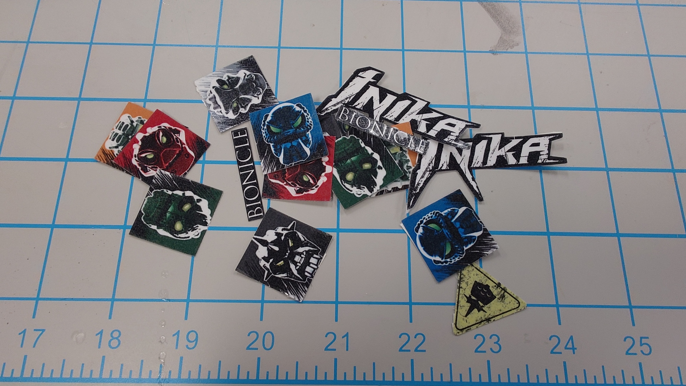
I went ahead and printed the sticker sheet I had, and used the Cricut that was available in the DKC (after getting the appropriate training for it) to cut them out, along with some extras just in case.
They turned out pretty good, but I still wanted the extras in case something messed up.
For most of these, I will still have to wait before I can use them, although for one of them, I can go ahead and get it added now.
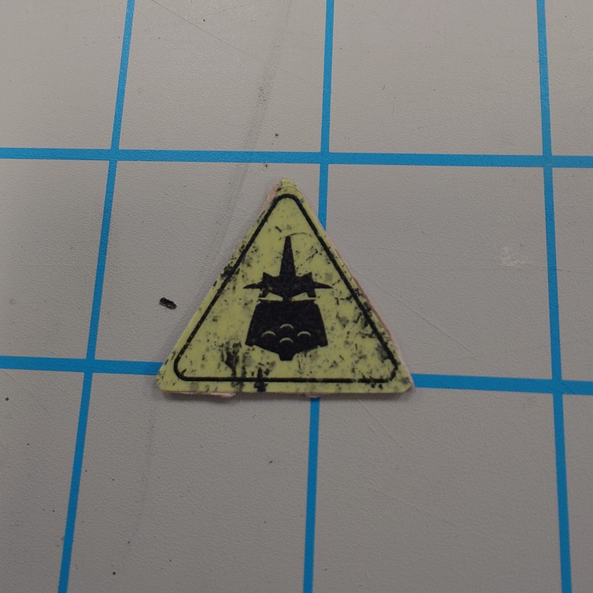
I used some cardstock and cut an outline of the sticker, where I then simply placed the sticker on top of it, which gave me…
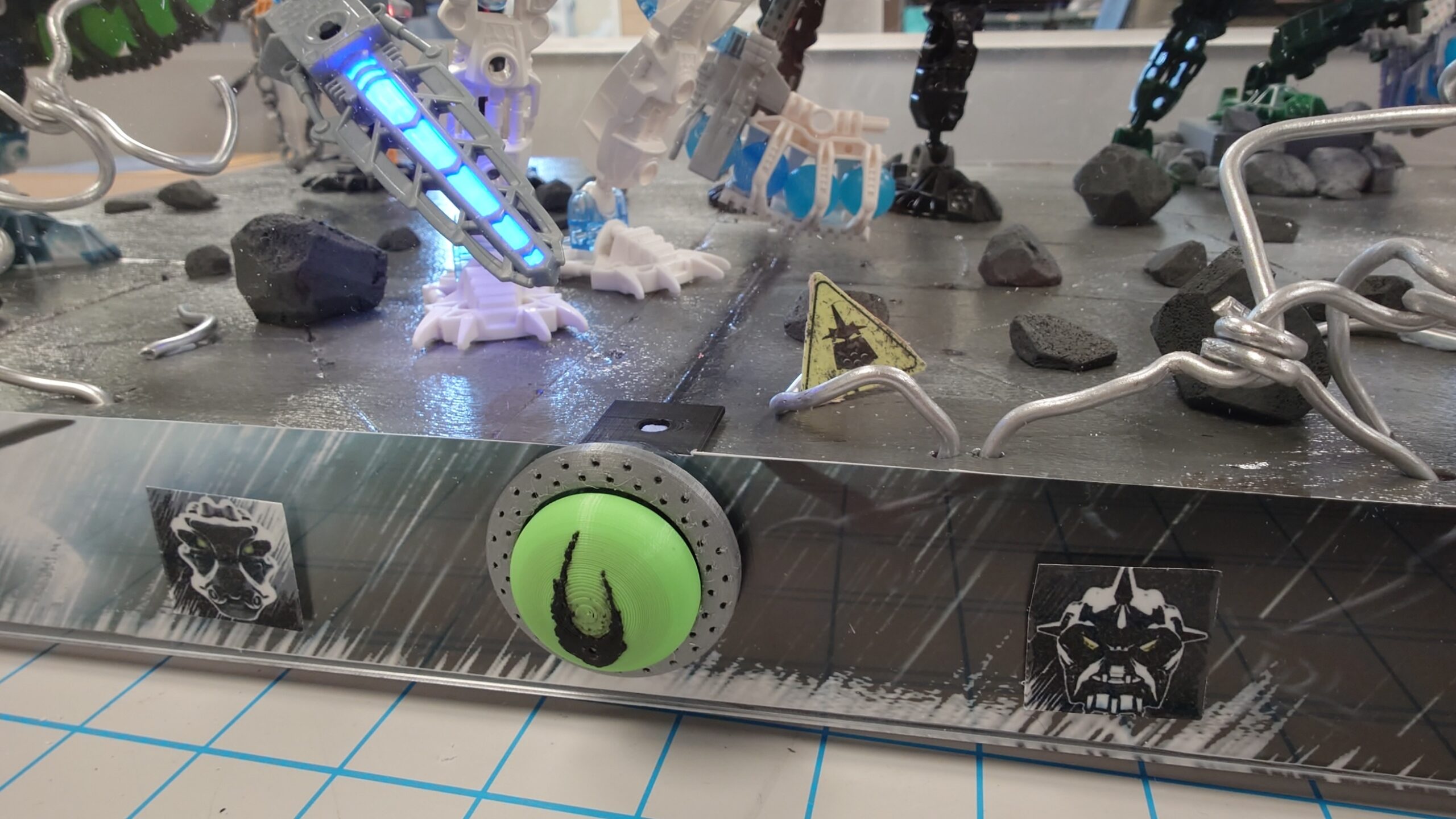
The weird Piraka hazard sign.
I personally think it almost looks exactly like a decal Lego would use officially, so I’m super proud of that.
But with this added thickness, I can easily just lay it down somewhere on the display base for that last bit of detail.
A Loss of Direction
It was about at this point that I started to get scatterbrained and distracted with other aspects of the project. I wanted to try out the Plexiglass to make sure it would fit, and try various methods to make it stick.
Originally, I started with magnets since I figured it would be easiest, but the DKC unfortunately did not have any that were strong enough to hold the Plexiglass in place, so I had to redesign.
After a short break, I came back to it and suddenly got hit with the idea to make a specialized holder that would slot the sheets into place. I sketched out the design, but I couldn’t figure out how I would make it attach to the platform raisers I already had.
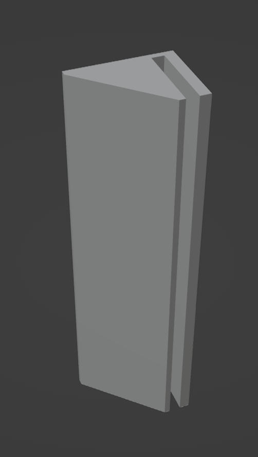
I got stumped on it for a little bit, but after another short break, I got struck with inspiration again. Instead of making an entirely new part, I could just incorporate the design into my already existing platform raiser!
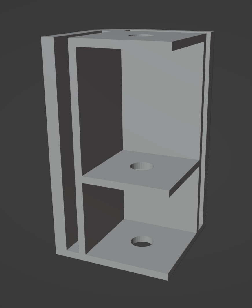
I quickly got to work in Blender, and created this (while also getting the hang of using proper modelling techniques! My model is no longer incredibly messy):
I didn’t realize it while making it, but this also keeps the profile super low and overall lightweight.
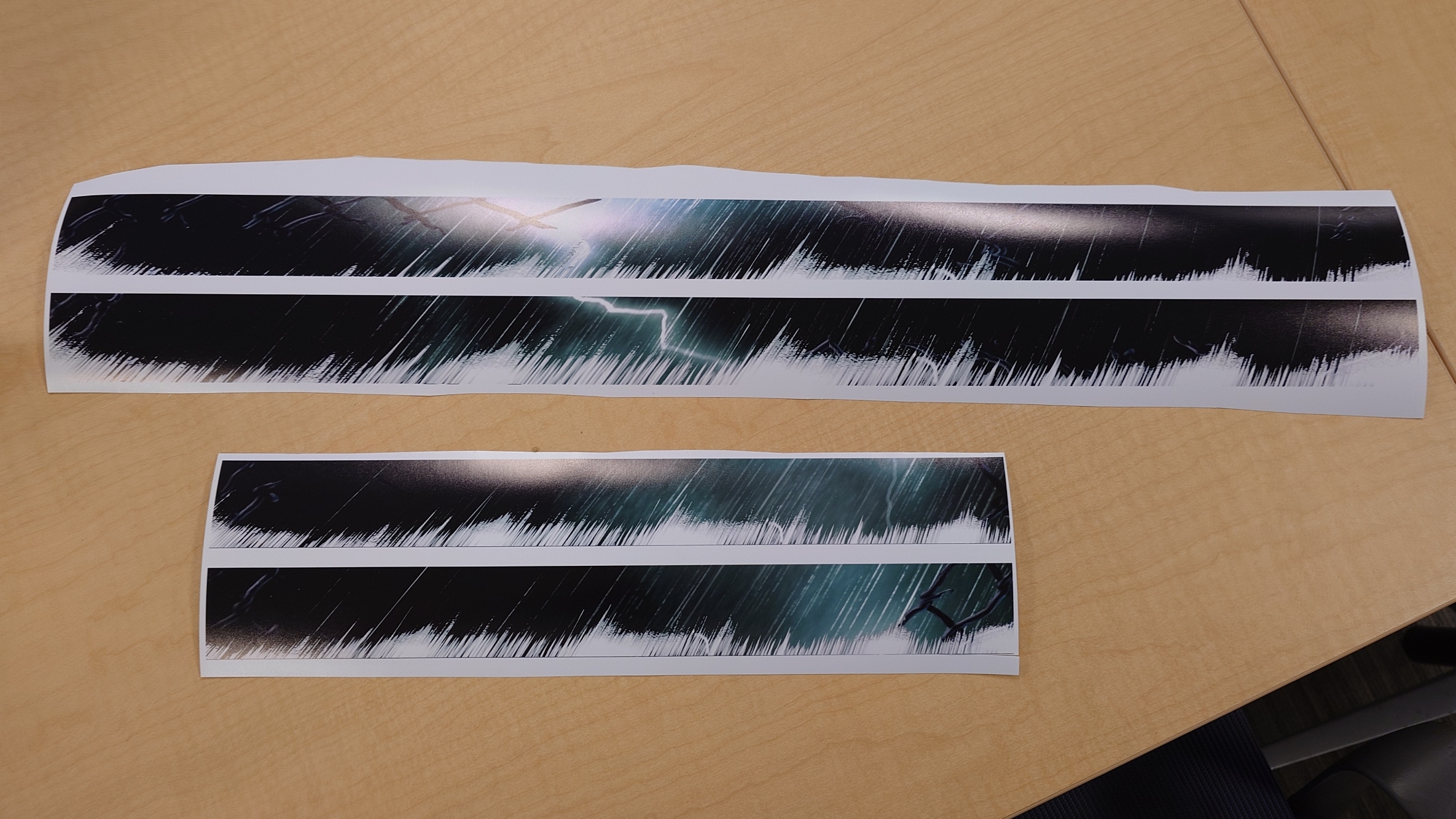
But while I set them out to print, I decided I would have time to go get the border trims printed as well, so I went out and got that done, courtesy of Cartland’s fancy glossy paper.
I’m more than satisfied with the results. The paper looks incredible, and I’m happy with my design overall.
It’s a much higher quality paper than what’s used in stores for Lego’s banners (generally), which is perfect.
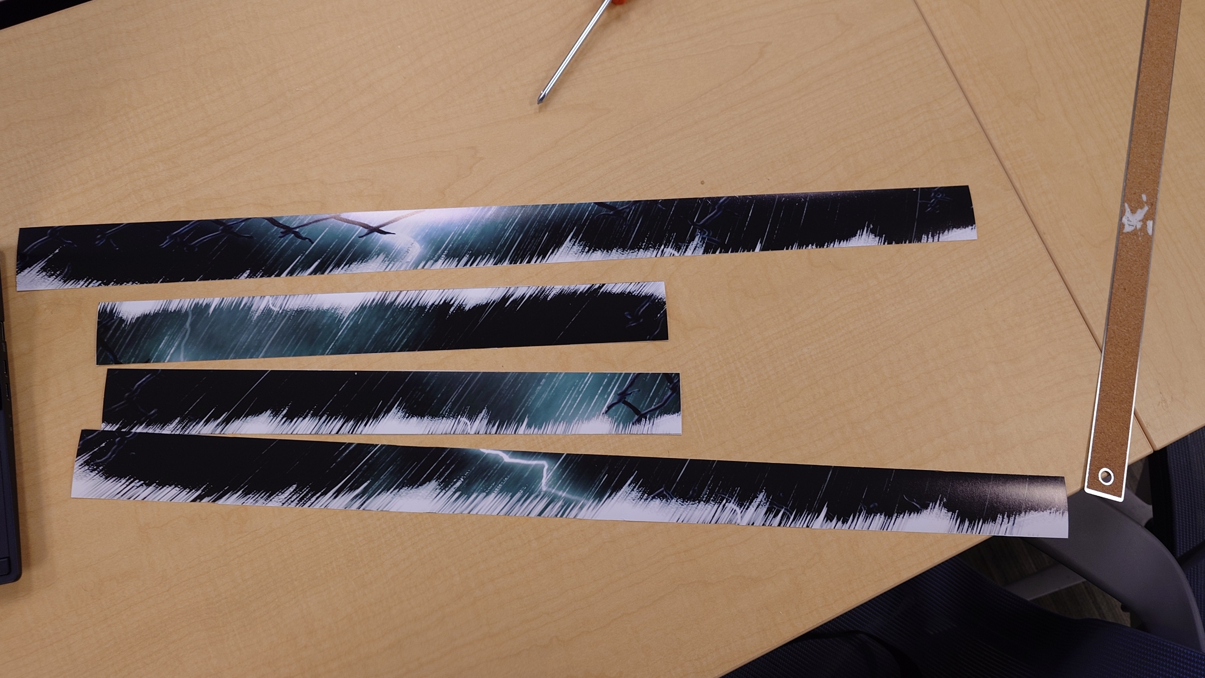
What isn’t perfect though is that I have to get these perfectly cut out without being able to rely entirely on the help of a paper cutter, since the longer strips don’t fit within the blade length.
I was able to get a good bit of them cut out by removing the bar on the paper cutter, and by going slow and careful with the blade, but I still reached a point where I needed to do it manually as the pieces just got too small for the blade.
I simply used a ruler and knife to line it up and cut it out. I did make a few mistakes, but nothing that was super-duper noticeable thankfully. It was a very tiring process however, and I much prefer cutting foam to this.
With those done though, I just need to wait for the new platform raisers to finish up.
A Proper Fit
Once they finished printing, it was easy enough to remove the bolts from the old ones and stick the news ones in. They fit just as well as the old ones did, as expected.
The next step is to apply the trims. I talked to Cartland for ideas on how to get it done, and he suggested using some glue, which I don’t think is a bad idea, but I had another one in mind to try out first.
I could easily slot the trims into the platform raisers alongside the plexiglass. It wouldn’t be very smooth, but I think I could make it work.
It isn’t perfect, but it is pretty good, and that’s fine enough for me.
Now, my original intention was to place the stickers directly on top of the trim so they would sit behind the plexiglass, but I don’t think they would’ve fit. The fit was already tight enough with just the trim and glass alone, and I think the added millimeter or so from the stickers would’ve made it impossible for it all to fit properly.
So instead I will have to place them on top of the plexiglass, which isn’t an issue, I just need to wait before I can do that, as I need to do some drilling.
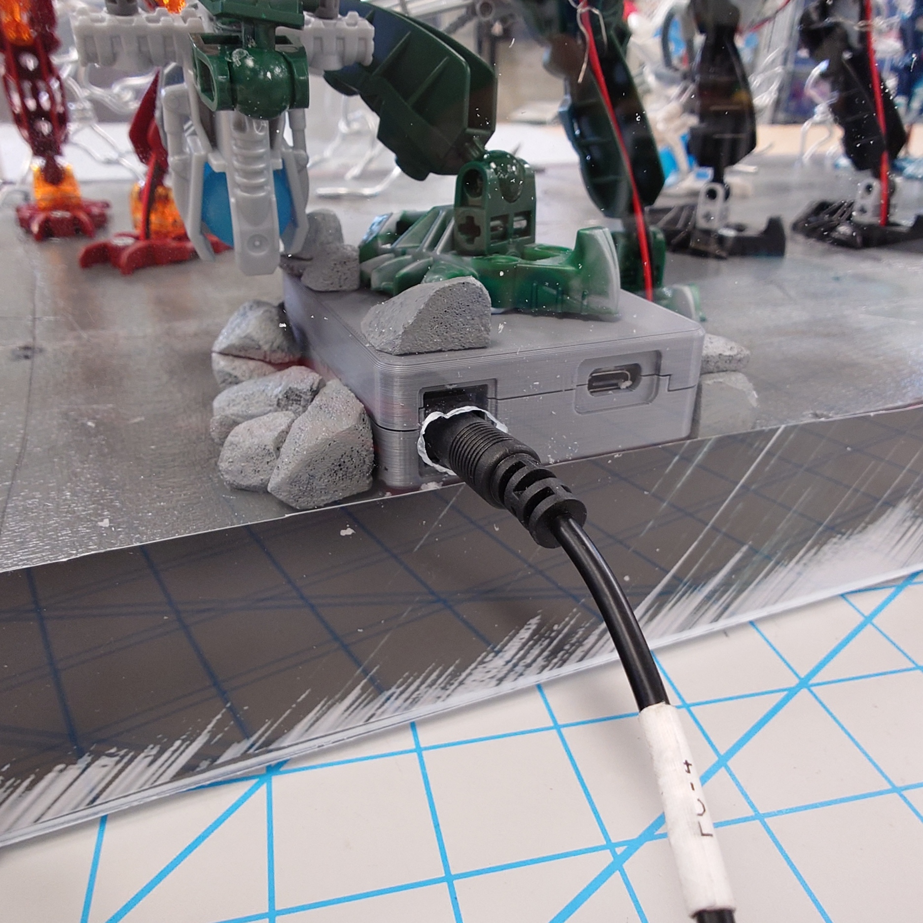
I need holes for both the button on the front, and the power supply in the back. One of those is going to be a lot easier than the other, but we carry on nonetheless.
I decided to start on the back since I could just use my hand drill to make the holes.
After a bit of work, it turned out messy, but functional.
So now I just need to do the same, but on the front.
I decided the easiest route would be to just cut a small square out that was the size of the switch for the button. It took a lot of finagling and a good chunk of time, but I eventually managed to come out with a result I was satisfied with.
And that, thankfully, marks the end of cutting into the plexiglass. It’s time to move on to the finishing touches.
Finishing the Fight
The first thing I did was add some rocks around the base to help it look more natural. I did a very quick cutting and painting job, but I think they turned out okay.
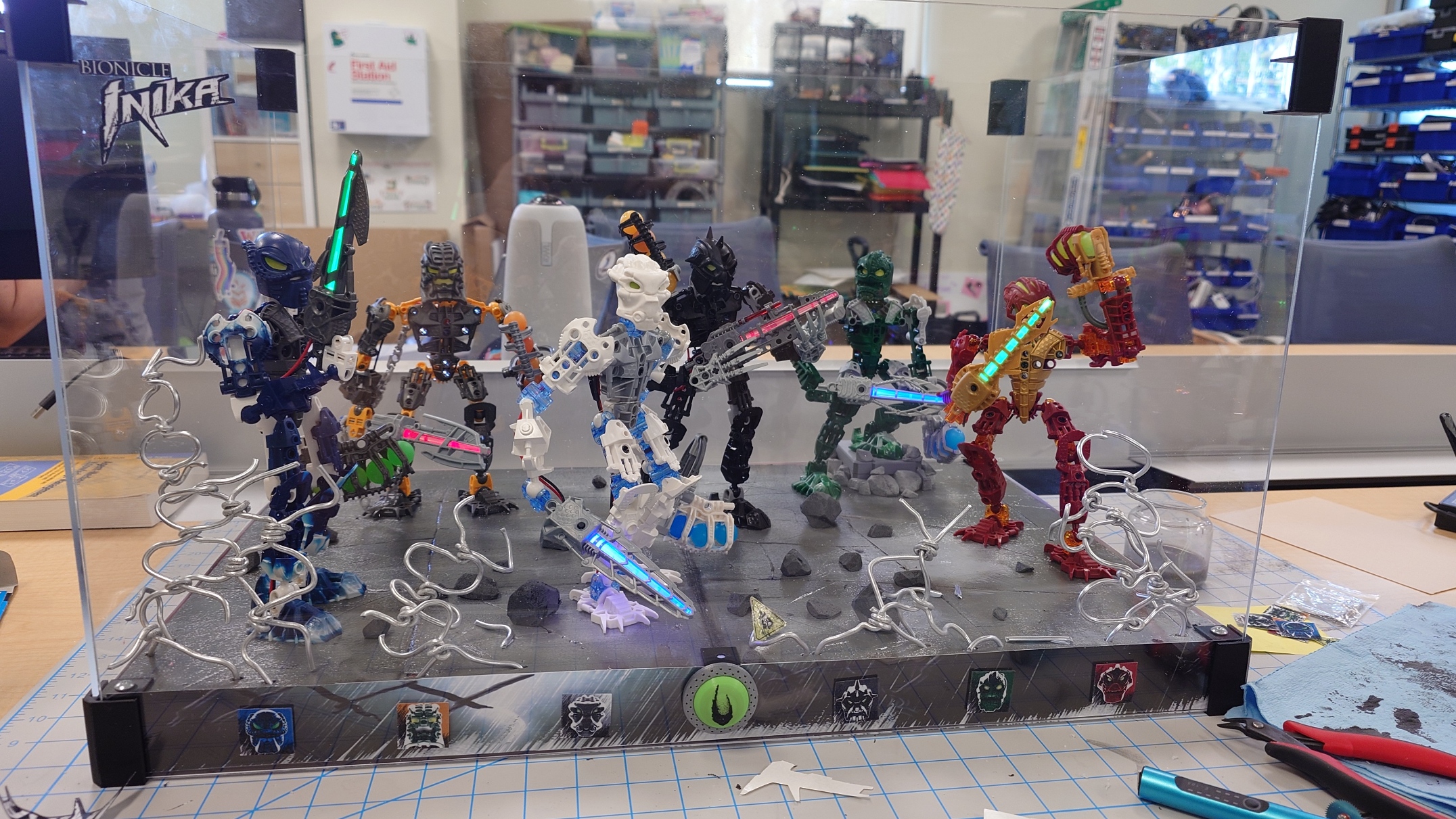
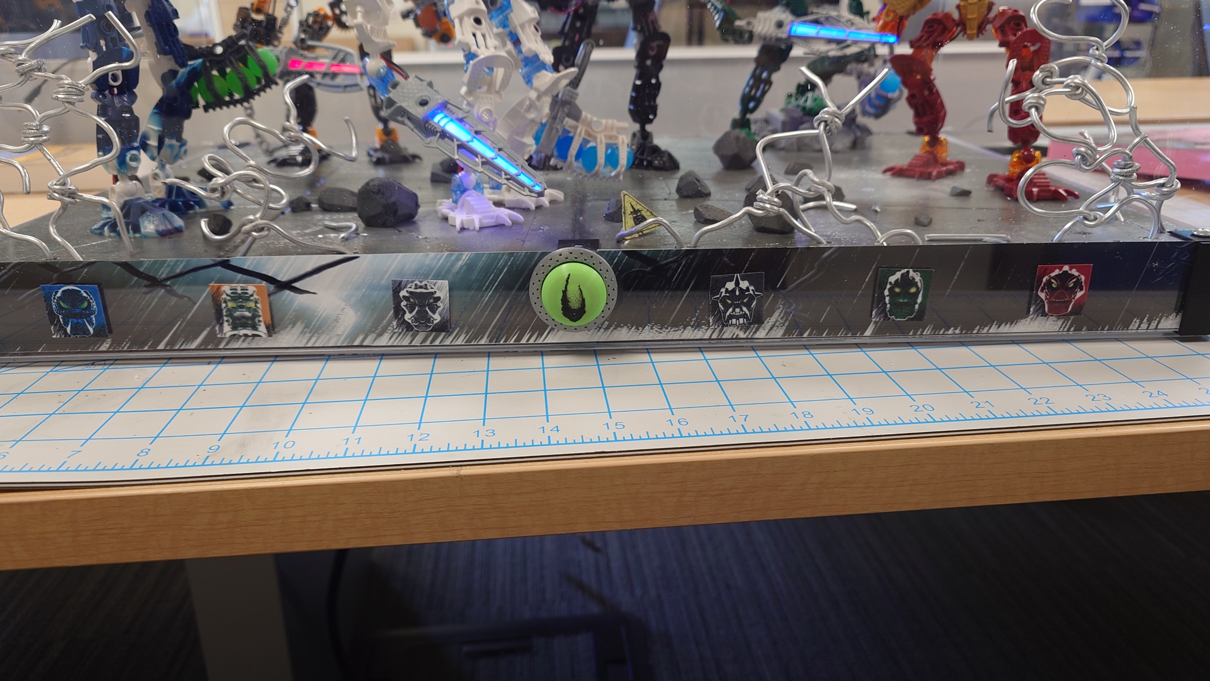
Next up was to apply the stickers. I decided on putting the logos in the top left, to mimic the actual canisters from the sets, but I was less sure about where I wanted to put the icons of the Toa.
On one hand, I originally wanted to place them on either side of the display, to help fill it out more, but I feel like it would leave the front too empty, especially with the button having to do all the work to fill it up. So considering that, I opted to place them on the front.
I definitely put some of the icons on a bit crooked, but hopefully it won’t bother me too much. I don’t have a lot of time to spare to reprint unless I absolutely need to.
With these small additions, that leaves the last task left: put the lid and bottom on and seal it all up!
Sealant
As I was measuring the sheets, I realized I will need a bit of extra support, as the plexiglass on the top dips down slightly, and it concerns me enough to do something about it.
To this end, I pulled up my platform raiser model in Blender again and tried to work off of that. My idea was to essentially take the raiser I have now, and translate the design to be on its side.
The print was going to take a while, so in the meantime I started working on cleaning up all of my various supplies I’ve accrued over the last few months. It’s been a very fast semester, I feel like. But I’ll save the retrospective for the end of this post.
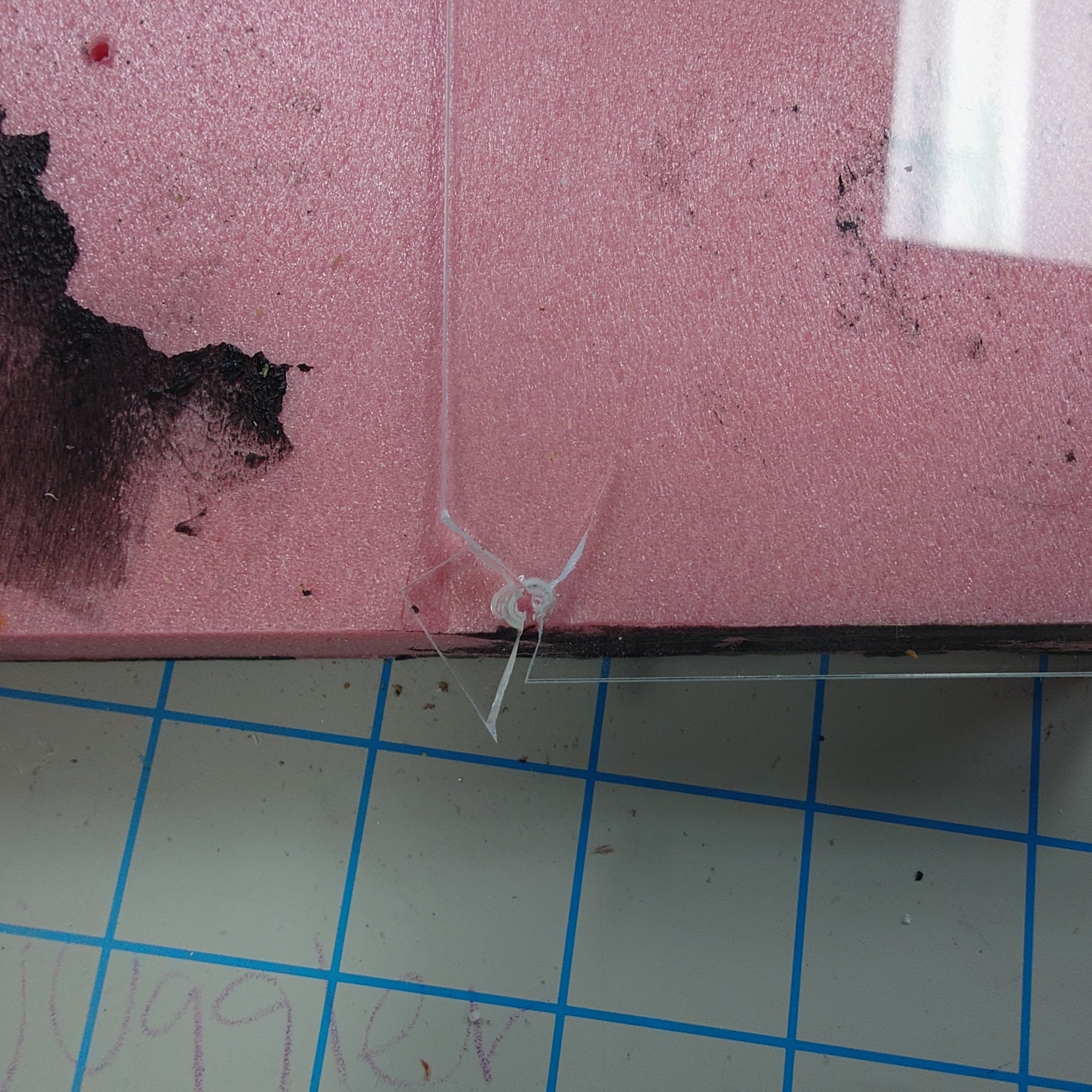
As soon as the helpers finished printing, I went ahead and tried to screw the plexiglass on. This came to a very quick halt as soon as I cracked it.
I was a bit upset, but I quickly thought back to when I did my research on this. The threat of cracking the acrylic glass was very high, and something that was always warned about. And yet I managed to forget it.
This scared me off from trying to screw anything else into it, and I immediately went back to the old reliable Blu Tack to keep the panels in place.
It’s not the prettiest solution, but I don’t have any time to brainstorm about it now.
But with those panels put on, it’s finally time to come to a close here.
Journey’s End
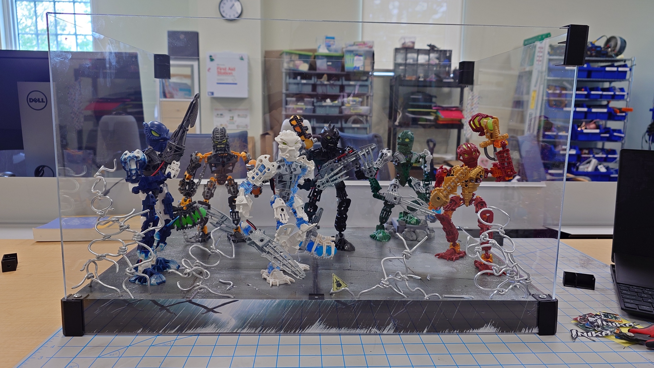
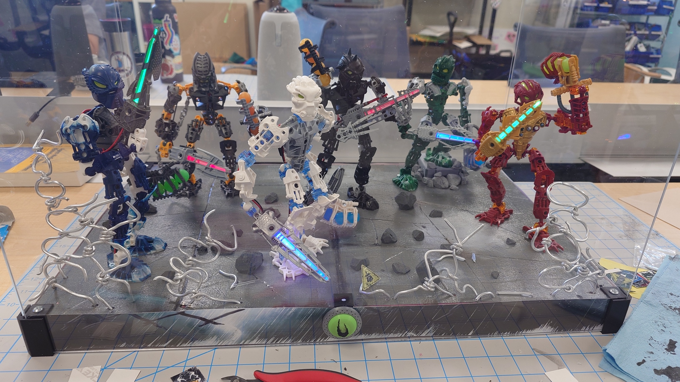
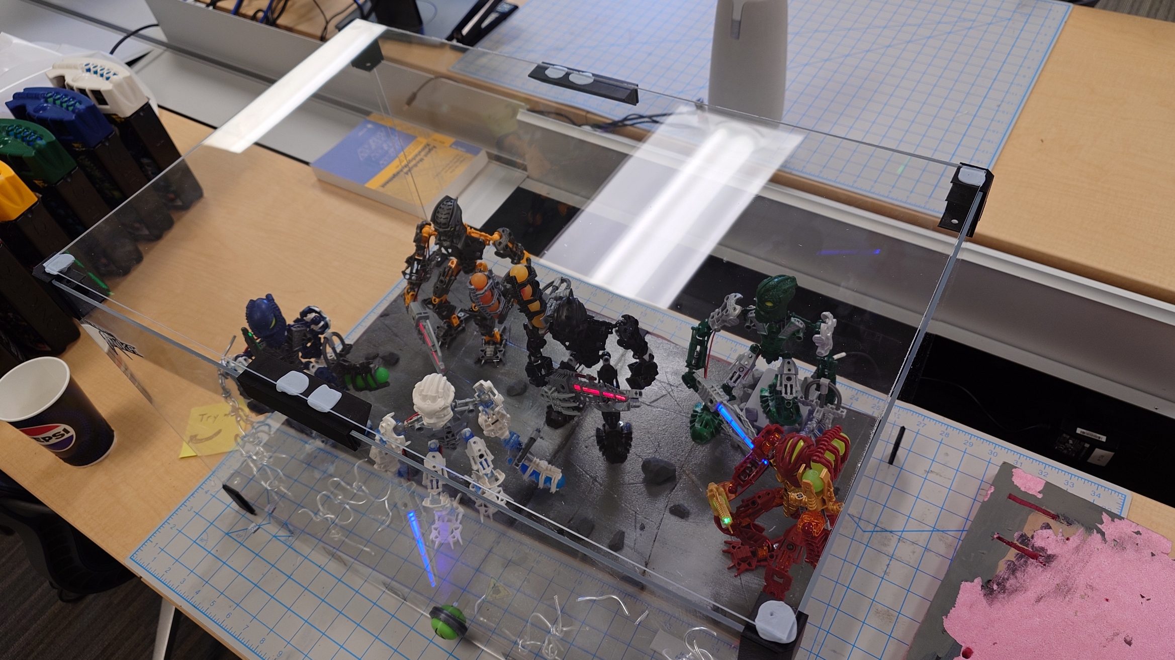
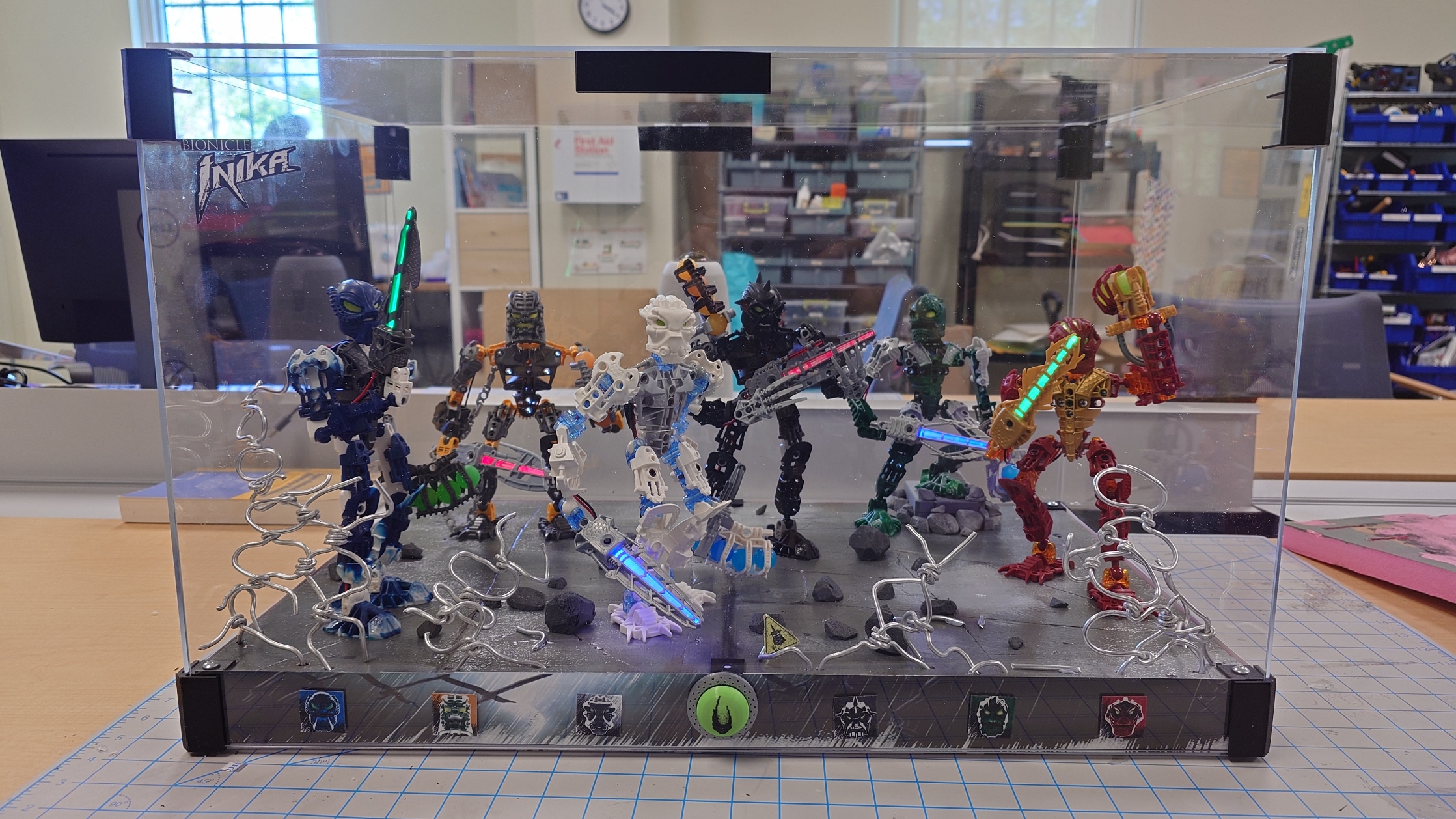
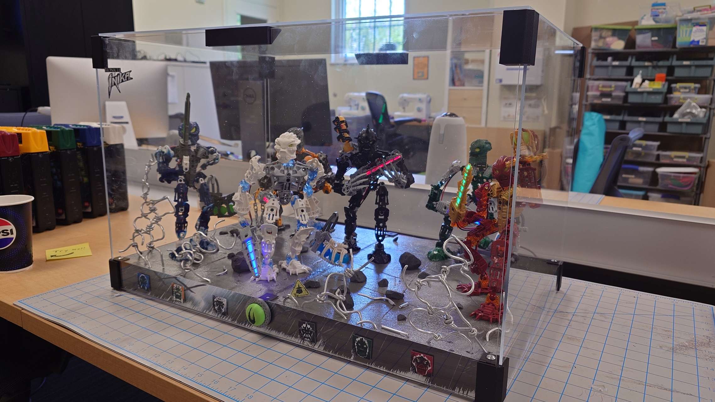
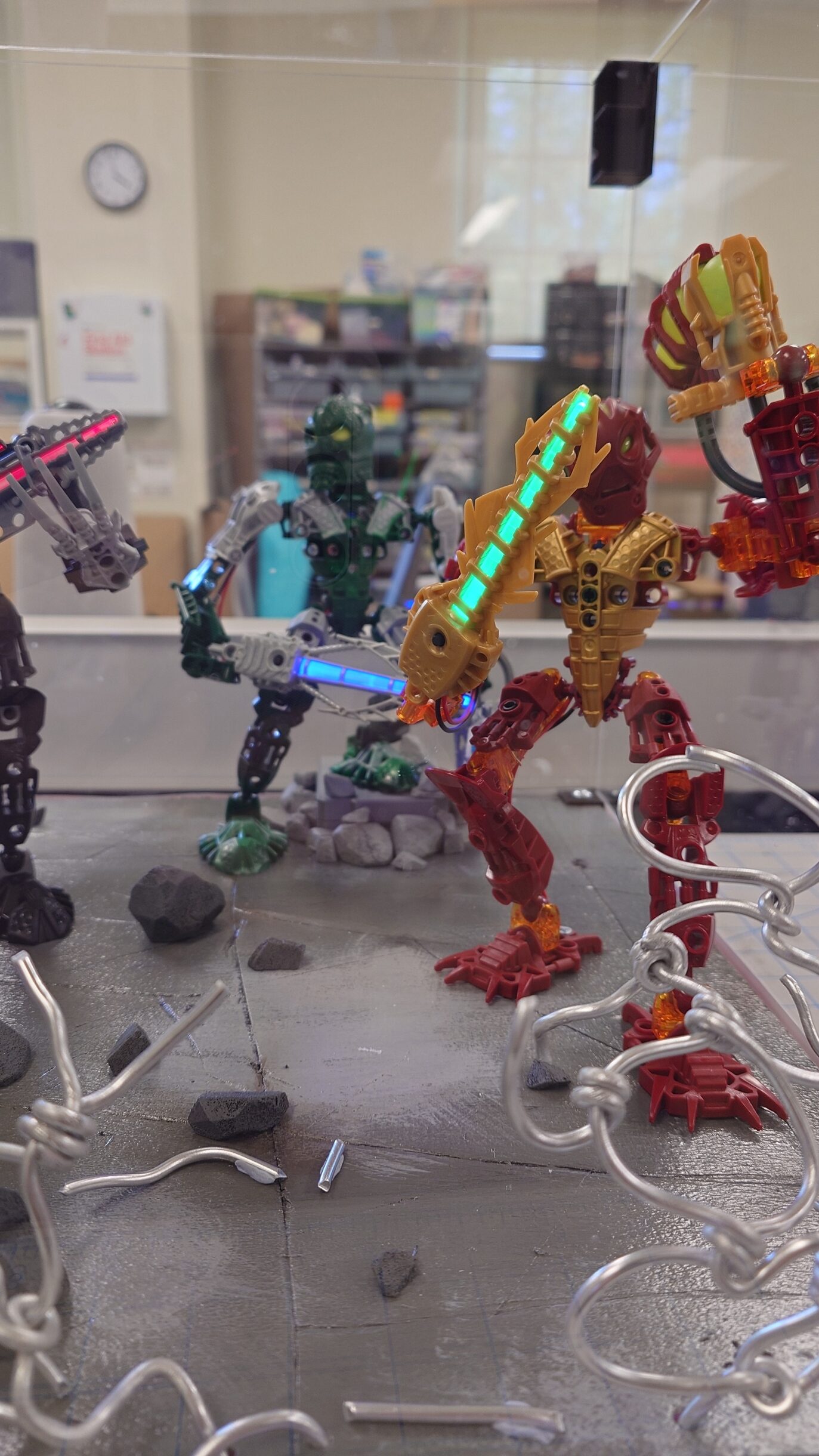
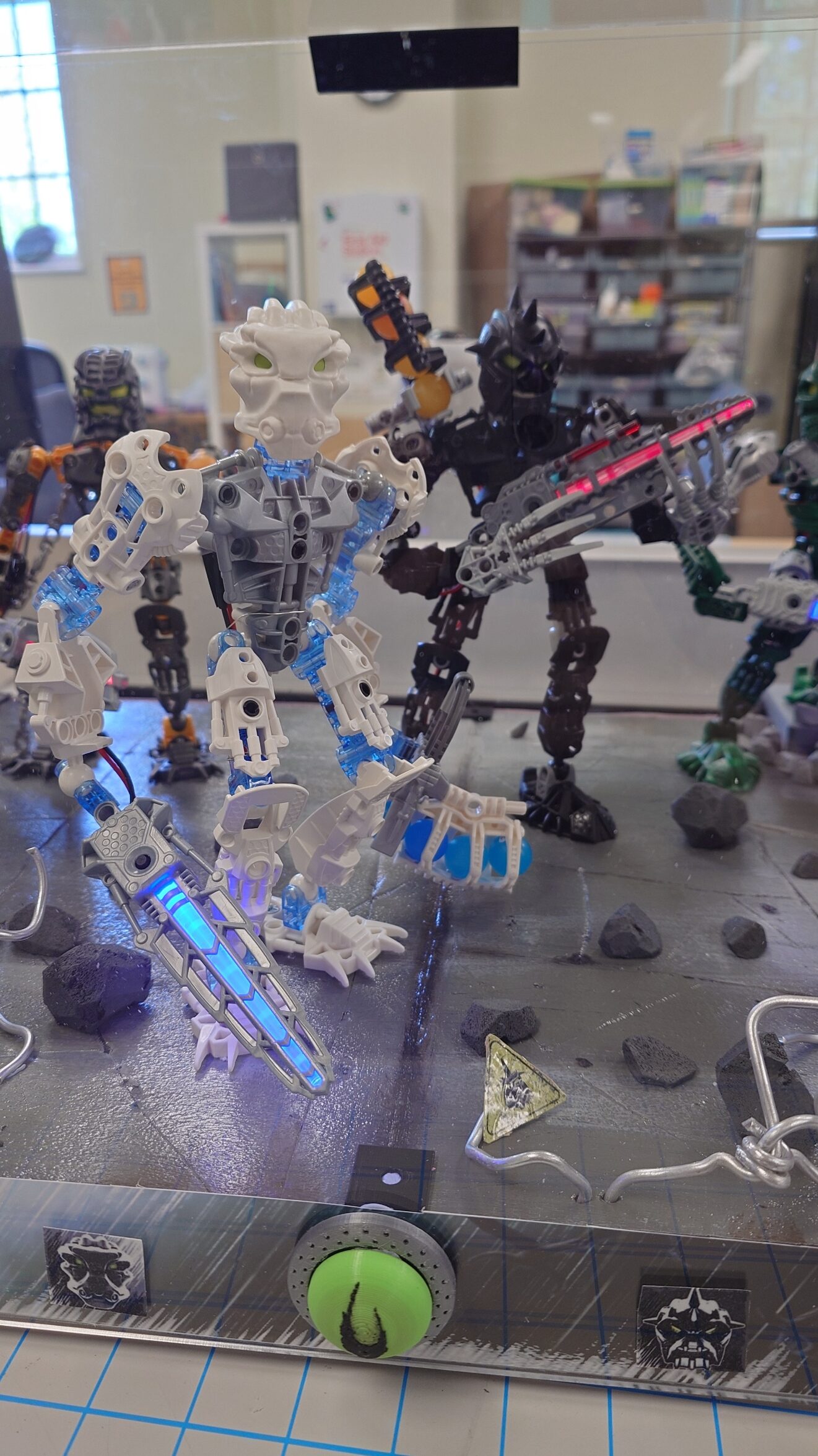
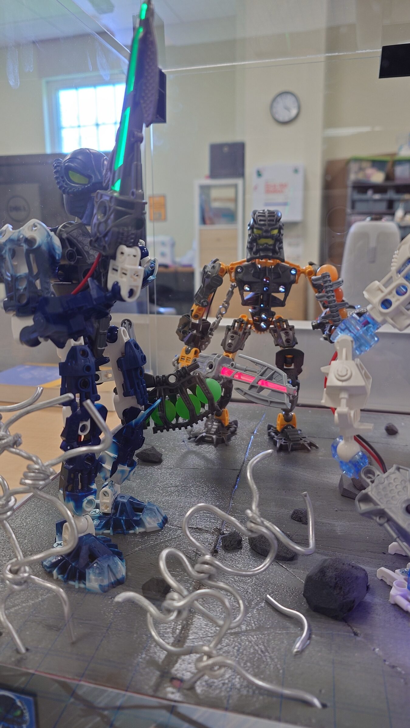
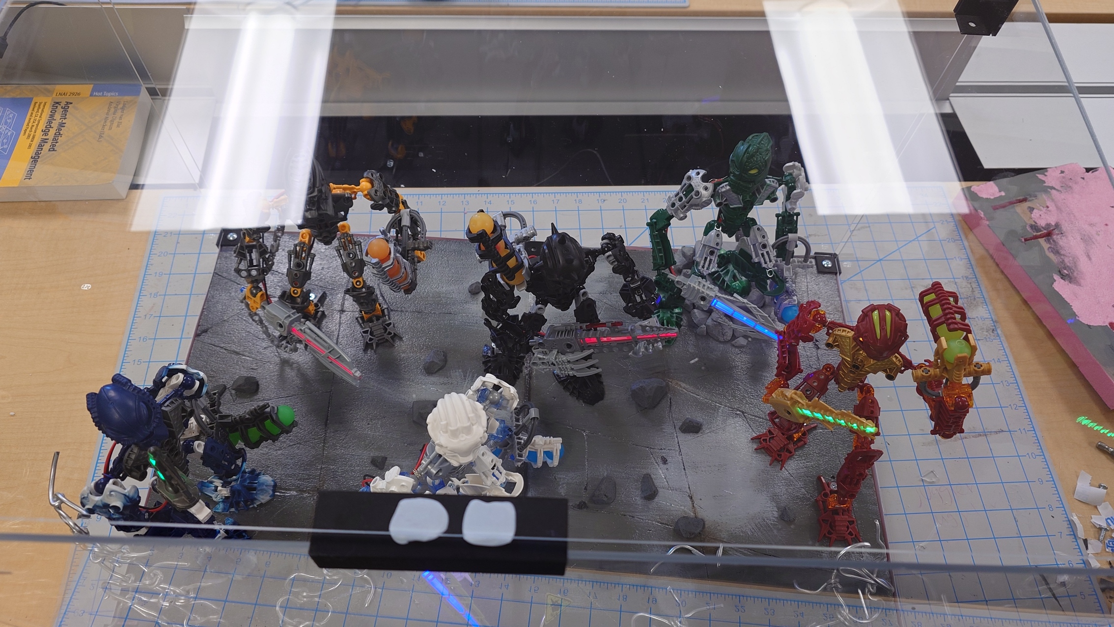
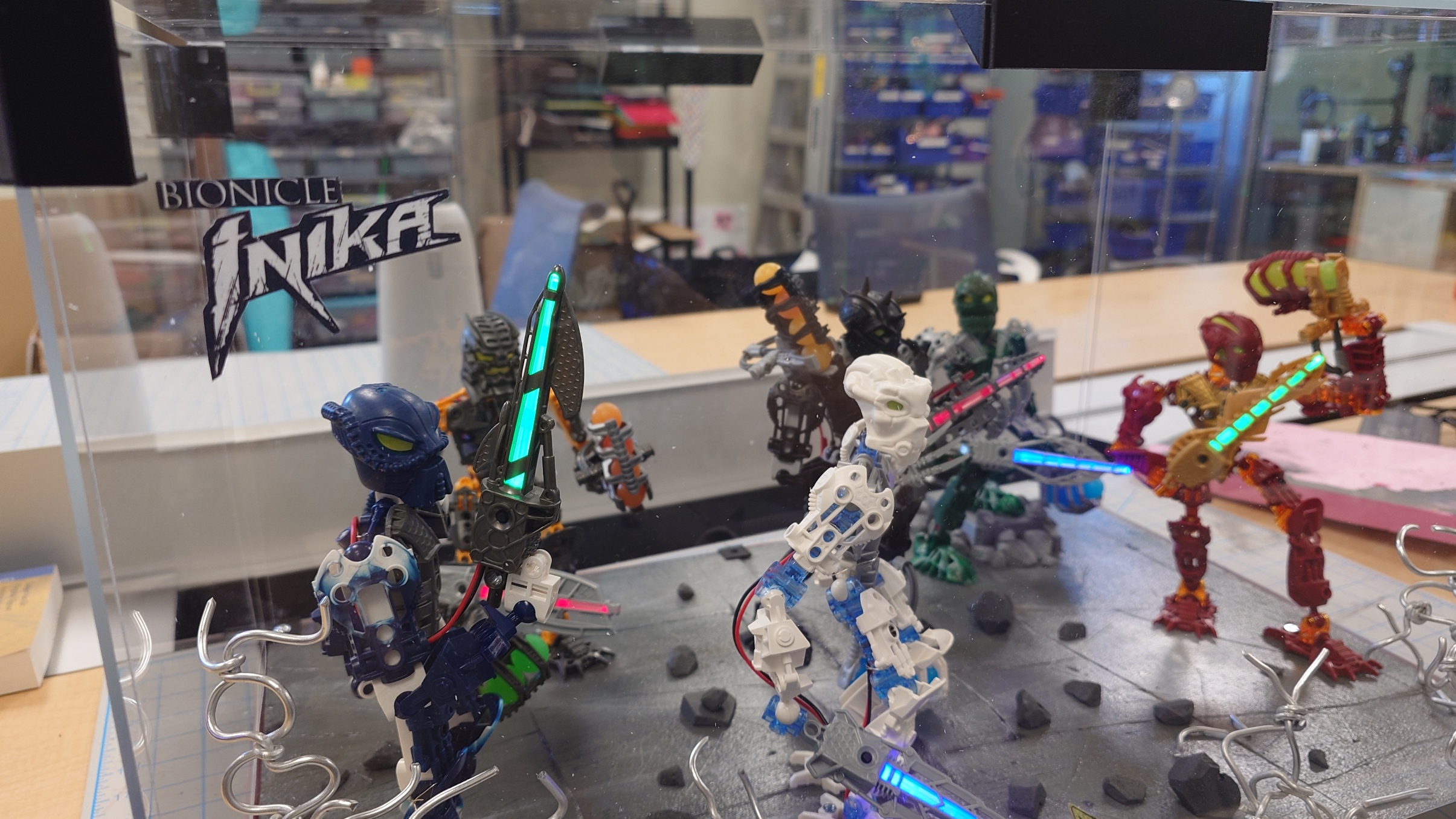
Shannon requested that I get “as many pictures of the completed project as I can”, so I’ll abide to that request now.
And of course, it’s time for the big function reveal, at long last. These lights have been working for a good few weeks now, so it’s time to finally show them off.
And with that, it’s time for a retrospective.
Like I said before, it’s been a fast few months. Spring semesters typically are though. This project was both a lot of fun, and also really tedious to do. I, rather surprisingly, didn’t make as many compromises as I figured I would, but maybe I just don’t realize them.
While I did mostly enjoy writing these blog posts, the novelty started to wear off in the last three weeks or so, and it became a chore. I do wish I had more fun facts to bring up, but I was limited by trying to keep the facts related to what I was talking about, which means I couldn’t do very many when all I got to talk about was the process of how I created stuff.
I know I’ll come to regret having so little details about some of my processes in the future, but hopefully by then we’ll have tools to extract memories from our brains, or something like that.
Being in the DKC this long has essentially turned it into home for me. If it weren’t for weekends, I probably would’ve spent more time here than my actual home. I liked getting to talk with Shannon and Cartland so often (and Jerry too, even if our interactions were brief), and I’m glad to have bonded more with all of them. It was also interesting seeing all of the people that came in throughout the days.
It’s funny thinking back to one of my meetings with Shannon and Cartland where I expressed worry about finishing this project too soon in the semester, as I sit here writing this only one and a half hour before the DKC officially closes… on the very last day of the semester. It quite literally took me every second.
I definitely could’ve been more efficient, but that’s just how I am. Some weeks were destined to be slower than others. But in the end, even only missing two days and leaving early only a handful of times, I managed to complete it.
I definitely wouldn’t mind doing another one of these, but I’ll need more time and definitely more money, which is scarce for me currently. But if I did do another one, I’m stuck between doing a single tube-style one for Toa Jovan, or doing a full display like this for the Piraka. Only time will tell if I do either.
I think that’s about everything on my mind regarding this. I know I’ll remember something else a week later, but oh well.
Throughout completing my duty in this process, I’ve gathered unity, and now it’s time I continue towards my destiny. There’s no better way to end this off, than with one of the final quotes spoken in Bionicle:
“All journeys must come to an end, but this time, there is a new beginning as well. There will be challenges to face and enemies to fight, but I know you will overcome. All that has gone before, my friends, has only served to give birth to this new day.
Let unity, duty and destiny be your guides. Be well, be strong, care for this world and for each other. Farewell.”
Week 14… It’s the end game now. Once again, no time to waste, so let’s get started.
A Bit Here and There
Last week we left off with some button business needing to be finished up. All I need to do is first print a test design to make sure I have the measurements correct, and then go ahead and print the final product once I have confirmed that.
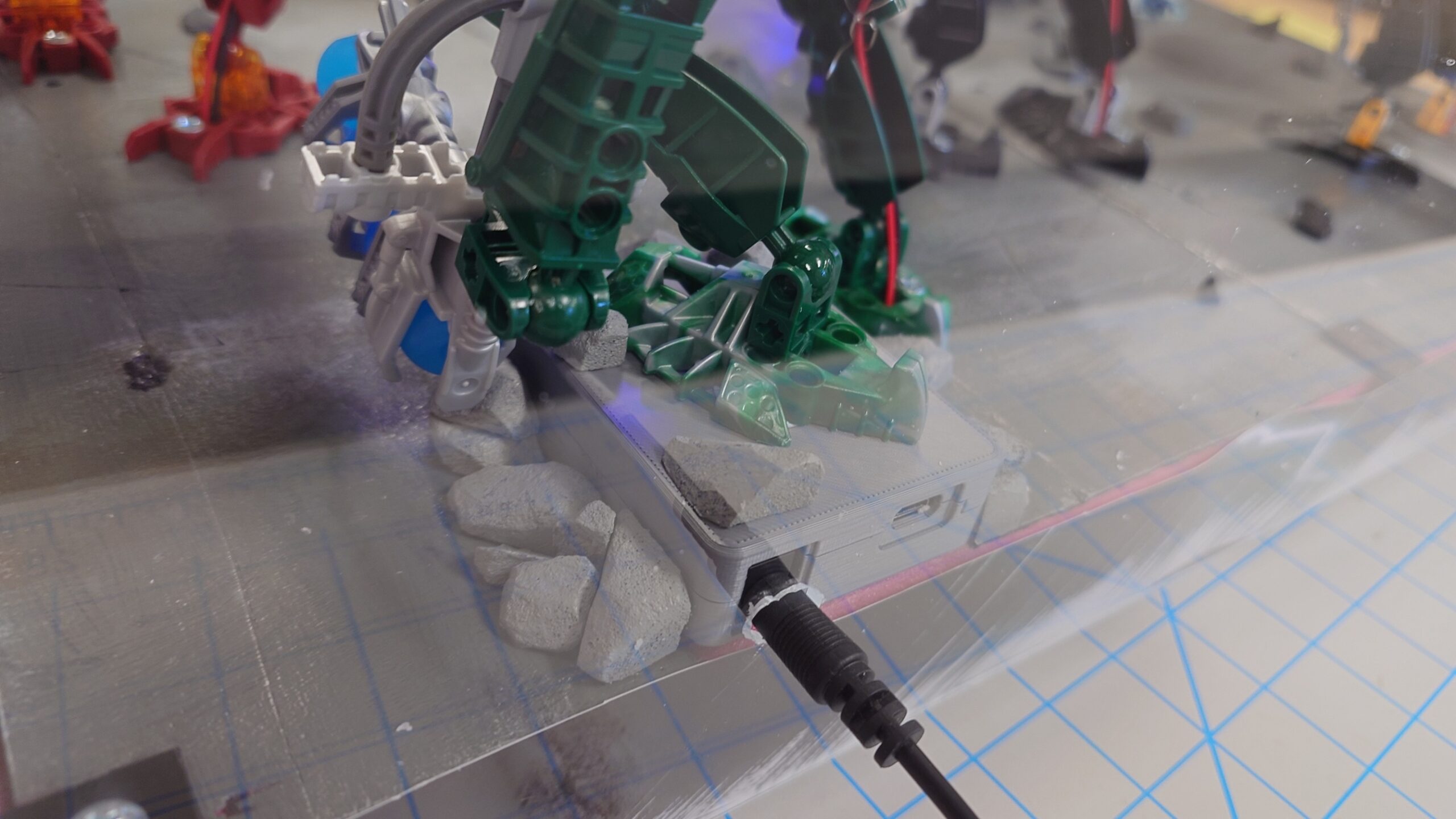
While it printed, I decided that it was finally time to put a few things in place, starting with Kongu and the Arduino board.
It ended up being a bit of a hassle to connect the cables, and I had a few of them break off from the circuit board that I needed to resolder, but eventually I managed to get it all set in place. The next thing I did was screw the circuit board on to the underside of the foam, which really helped with the cable management issues.
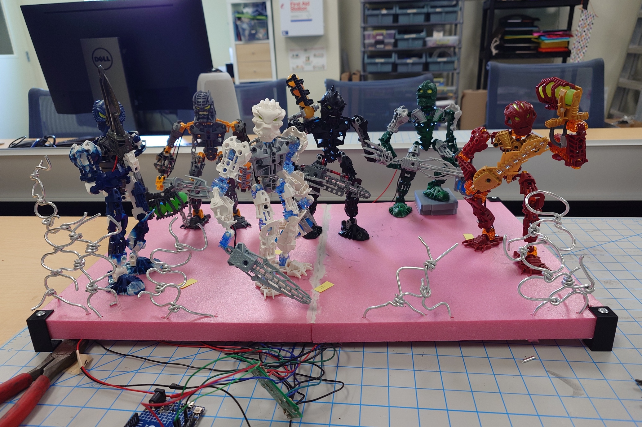
And then I went ahead and finally attached the rocks, and a bit of extra pieces of the chain-link fence for more decoration.
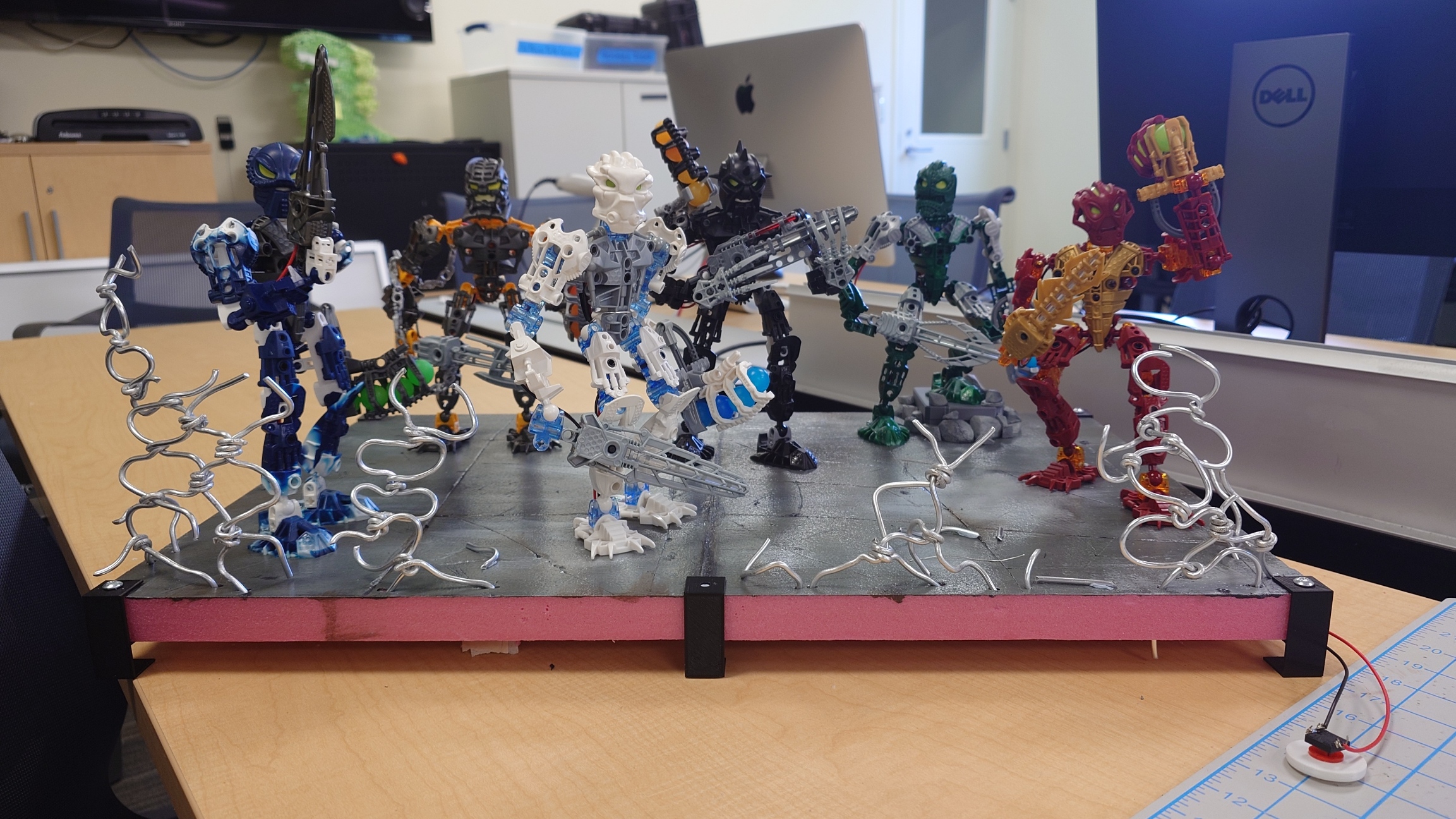
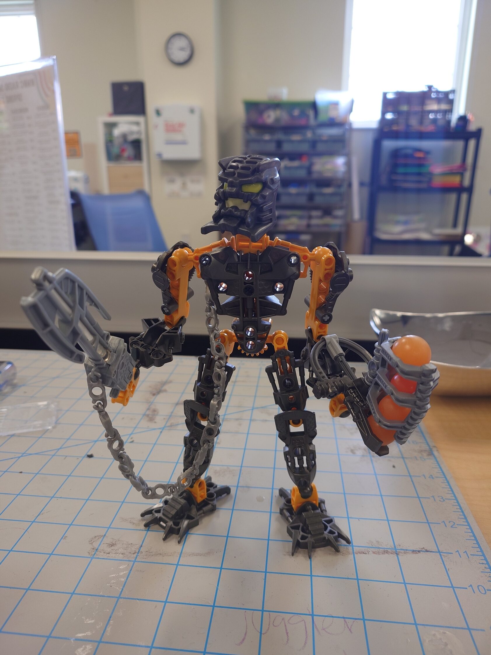
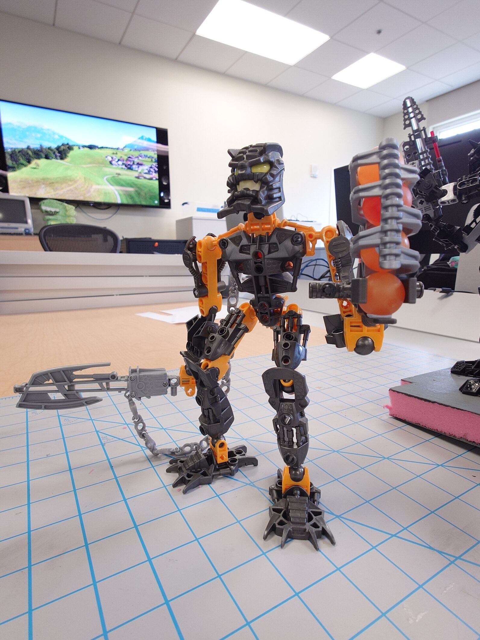
Adding all of those changes together gave me this result:
They’re finally starting to look like a true Toa team.
I’ll definitely want to carve some extra rocks to scatter around the base some more, but I’ll save that for last so it doesn’t cut into my valuable time.
But with that said, the next thing to work on is the decal, at long last.
Retro Fashion
I got the measurements set up in Photoshop, and while I have a general idea of what I want to achieve for the decals, I wanted to make sure I did it 100% correctly. And thankfully, I didn’t have to do it by eye alone.
One website I frequent is the BioMediaProject.com (currently in the process of moving to MaskofDestiny.com), home to all things Bionicle. From archives of the original Flash and retail games to specific marketing materials only meant to be seen by Lego employees, it’s an absolute haven for people like me.
Part of these archives includes some of the style guides that were used by Lego and companies it outsourced to, to make sure their branding stayed consistent. One for each year, save for 2002 and 2010, the years 2006-2008 are grouped together in a special “e-style guide” (found here) that unfortunately runs off of Flash, which made it somewhat of a pain to open.
Nonetheless, using an emulator, I was able to view the contents inside. Included were the specific guides for the years of 2006, 2007, and 2008, along with a general introduction to both the story during the time period, and also a general guide to Bionicle itself.
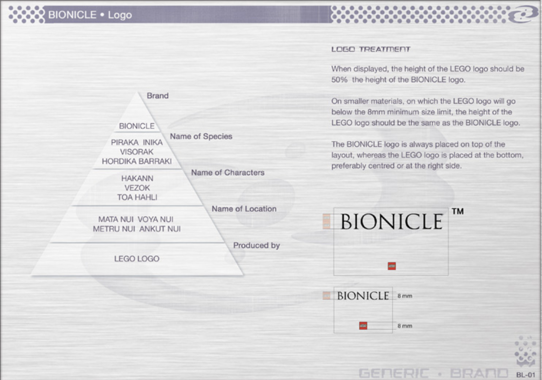
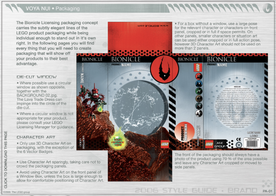
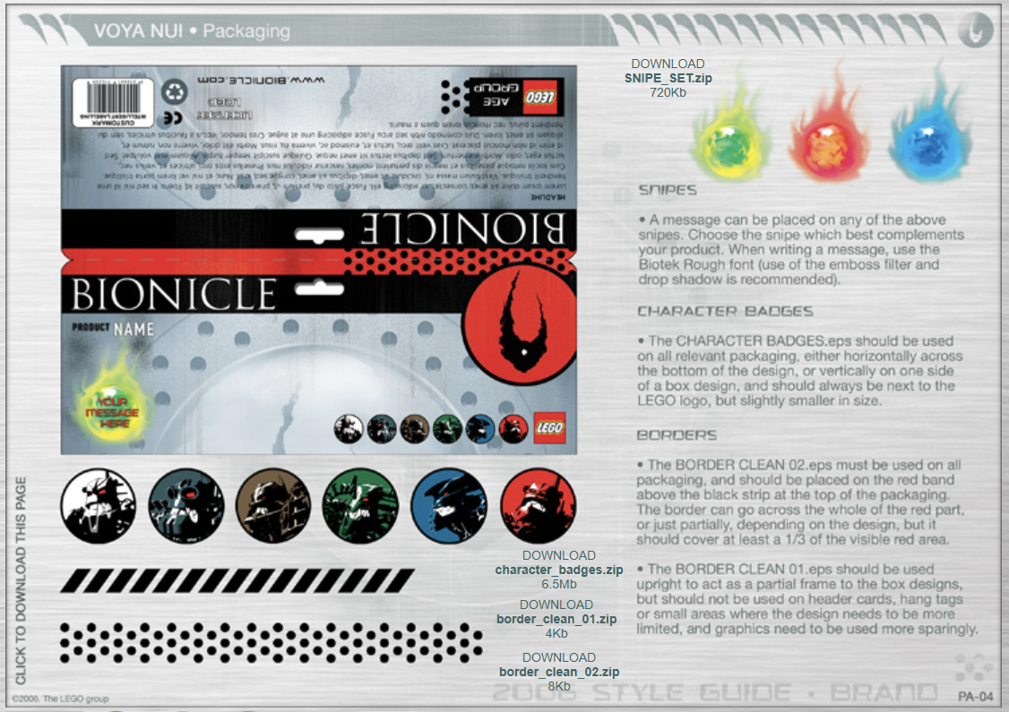
There’s too much specifics to go over here, so I do highly recommend taking a look at it for yourself. For the purposes of this project though, these are some of the pages that will serve the most useful to me:
General style guide displaying how large the logos should be
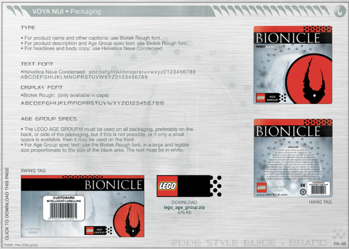
2006 packaging guide displaying general layout
2006 packaging guide displaying how borders should be set up. While it shows the Piraka here, this can be applied to the Inika too
2006 packaging guide showing the use of typography
Unfortunately, all of the downloadable content linked in these images are lost, for the most part, but there are other ways to get some of them, either through recreating them myself, or by taking other Photoshop files that contain the assets.
This is also not everything that I will be relying on, it’s simply the most interesting parts of the guide. Beyond the guide itself, I also have the physical canisters with me that I can reference. No better of a guide than what was officially released, after all.
But with this all gathered, I took some time to begin work on the display banner.
While creating it, I decided that, instead of trying to measure everything constantly and make sure none of the logos or icons go somewhere I don’t want them to, it would be much easier to print out the background on its own, and then print out any extra decals I want as stickers! Following this pathway made it much, much easier for me to create it all.
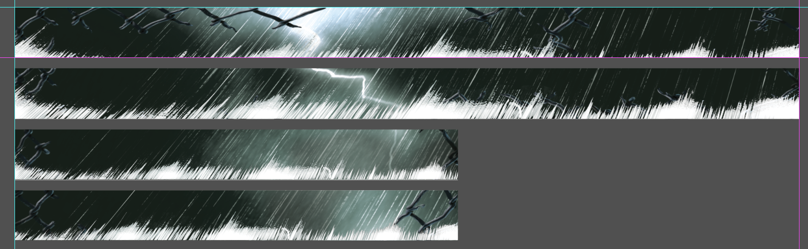
I first got the background that would host everything I wanted, which I decided to model after the background on the Inika canisters and promotional material:
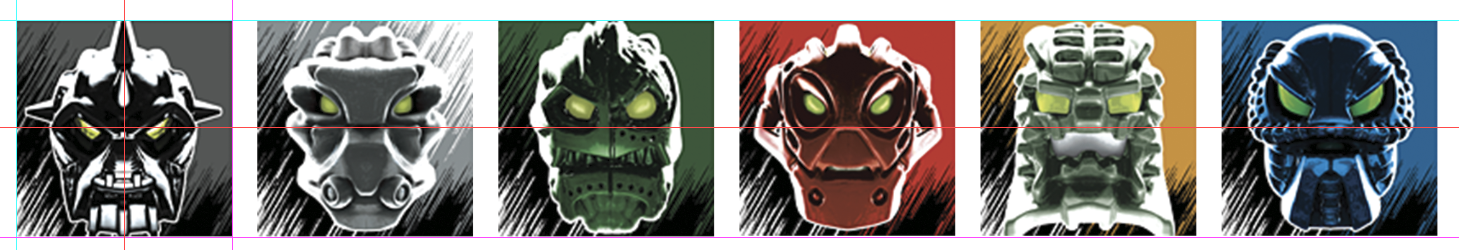
From there, I created a new canvas to host all of my sticker designs. I started by adding the Toa Inika icons that I’ve always loved:
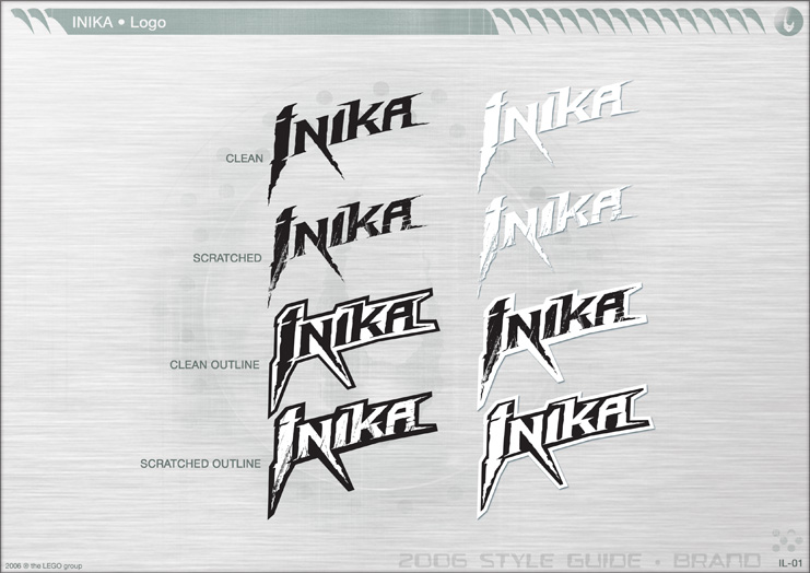
I also wanted to add both the Inika and Bionicle logo to the display. The Bionicle logo was easy enough, even though BioMediaProject didn’t have the specific one used in 2006, the biosector01 wiki did. For the Inika logo though, I wanted to use the same one from the canisters. On the design document, it has the “Scratched Outline” label.
However, it wasn’t so straightforward. I thought that BioMediaProject would have it, and that would be the end of it, but strangely, the only Inika logo they host is the “Clean” one from above, not outlines, no scratches.
And as I said before, all of the download links in the design documents are broken, so no luck there. I got a bit desperate, so I just kept trying to search to see if anywhere else hosted the files from it, but there was still nothing. I did, however, come across biosector01 again though, and amazingly, they had a high-quality version of the “Scratched” version of the logo.
I was baffled, nowhere else had the logo in such a high quality, so I honestly have no clue where it came from, but I’m very thankful for it. My job wasn’t over though, as I needed the outline, partially for styling reasons, and partially because the sticker paper can’t print transparent parts.
I tried using the “Stroke” modifier in Photoshop, but it didn’t give me the same results as the official logo, so instead of trying to make it work, I just traced the outline with the pen tool and made it fit the logo I had.
It’s pretty close, but there are very minor imperfections, that do bother me. But I’m willing to leave a bit of errors, since it won’t be super big anyway.
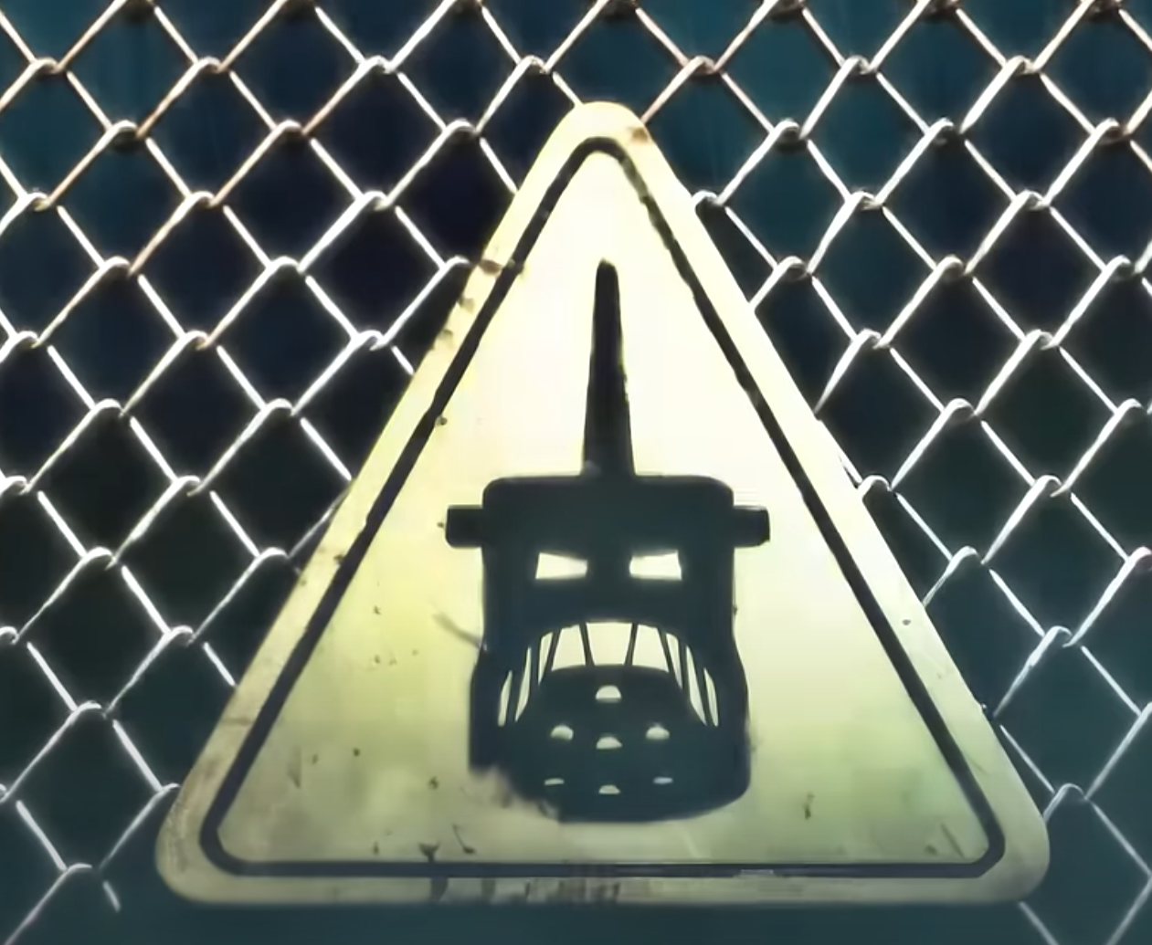
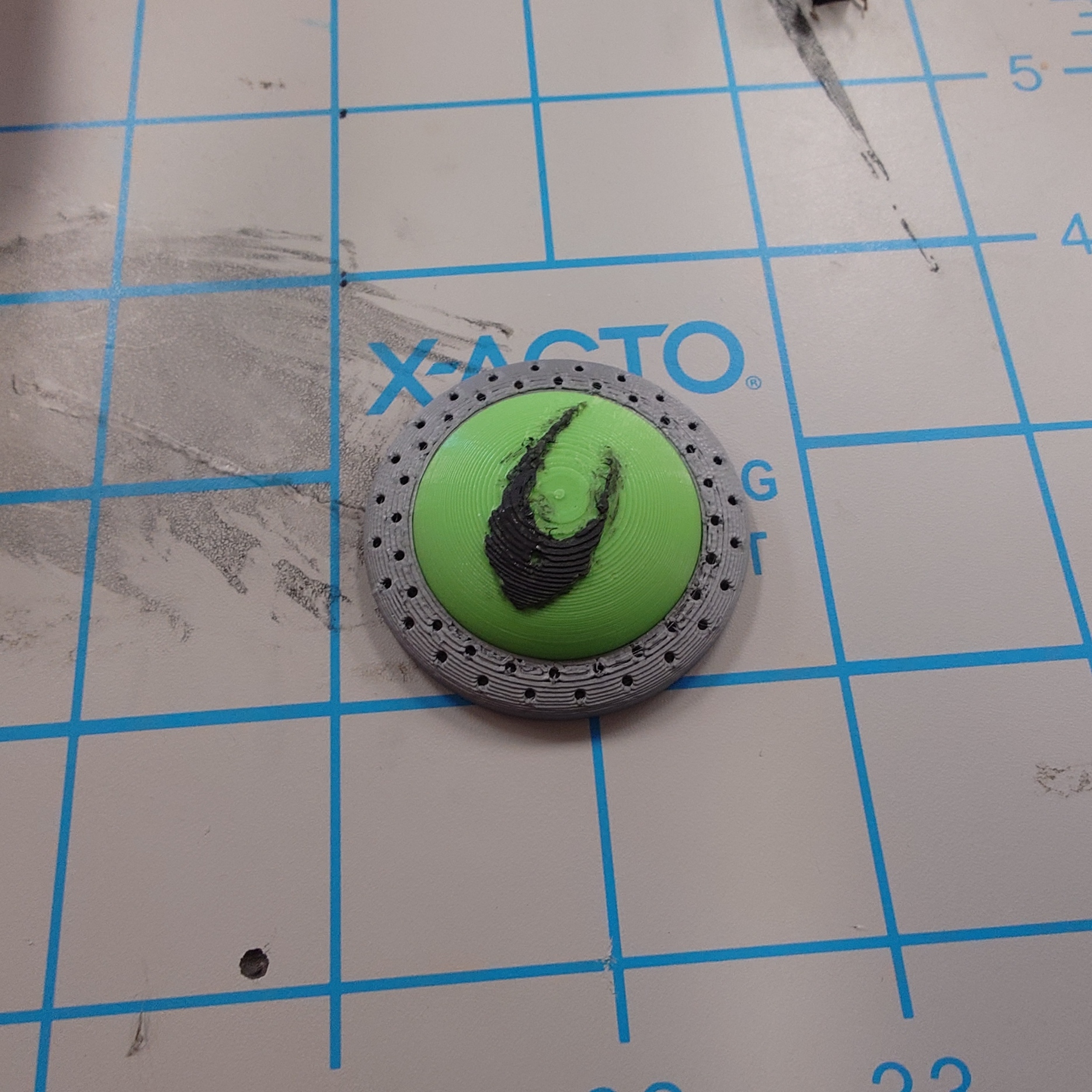
While working on the stickers, I had another idea of something I wanted to add. The Piraka hazard sign from the commercial!
It’s a little goofy, because who could this possibly be for, who could’ve put this up? Maybe the Piraka just want to mark their territory that much more. Regardless, I think having this sign be a part of all the broken fences would be a really nice detail, so I got to work.
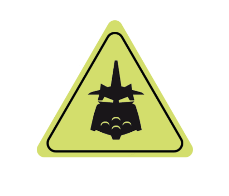
I knew I would have to recreate this one, as there’s no way the original texture would just be floating around online, at least easily. The triangle and its outline were easy enough to do in Photoshop, but the Piraka head itself was a bit tricky.
It is very clearly a silhouette of Vezok, but there’s no icon that looks like it. Some of the Piraka icons are pretty abstract (how is Hakann’s symbol a representation of him?), and while Vezok and Thok’s symbols look similar, neither one shows their teeth like in the commercial.
This tells me that the sign was custom made, but it’s no issue. I decided that just using Vezok’s icon as is will still looks pretty good, so I made the following:
I could probably add teeth in, but I’ll do that only if I really don’t like this design.
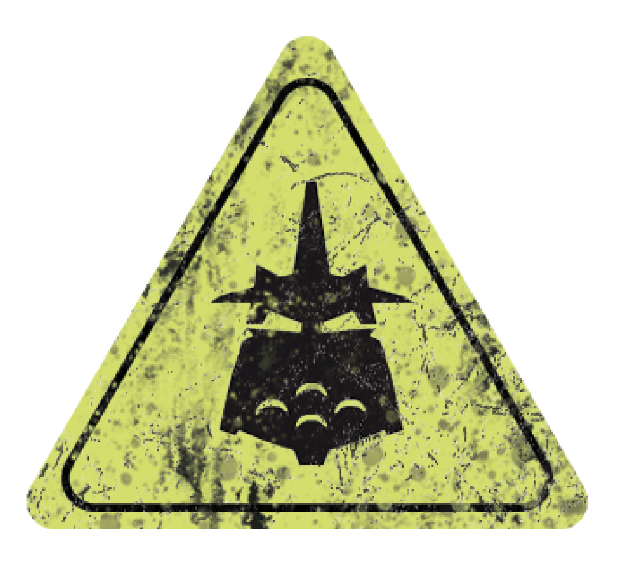
Nonetheless, I’m still not done with this sign. It’s much too clean, especially since it’ll have just been attacked and blasted off of its fence, so I remedied that with some basic dirt and scratch textures.
It’s got a lot more going on than the sign in the commercial, and I think it’s a bit cluttered, but it’s still recognizable, which is all that matters for me.
With all of this together, I’m ready to print on paper, but there’s something to attend to first.
Pushing Buttons
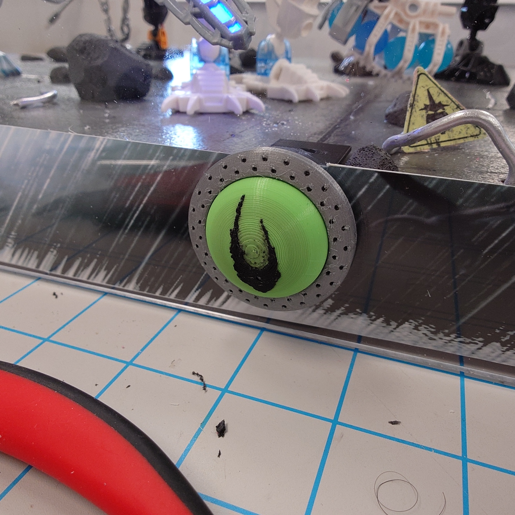
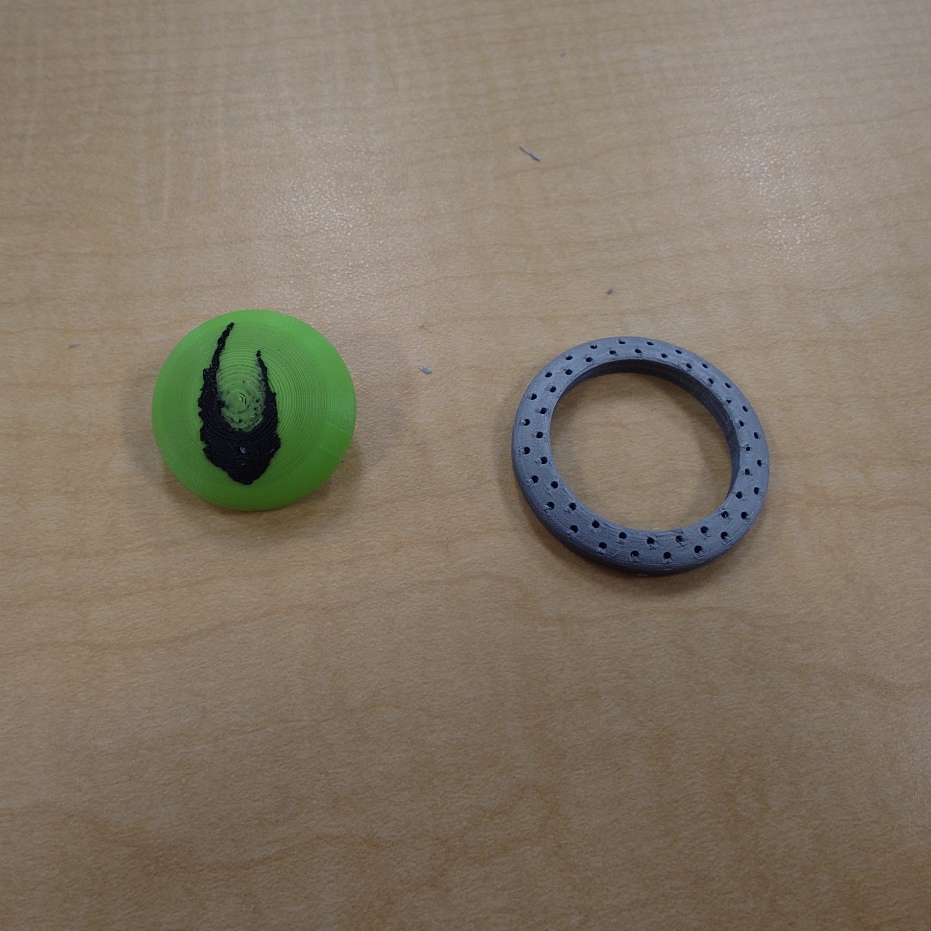
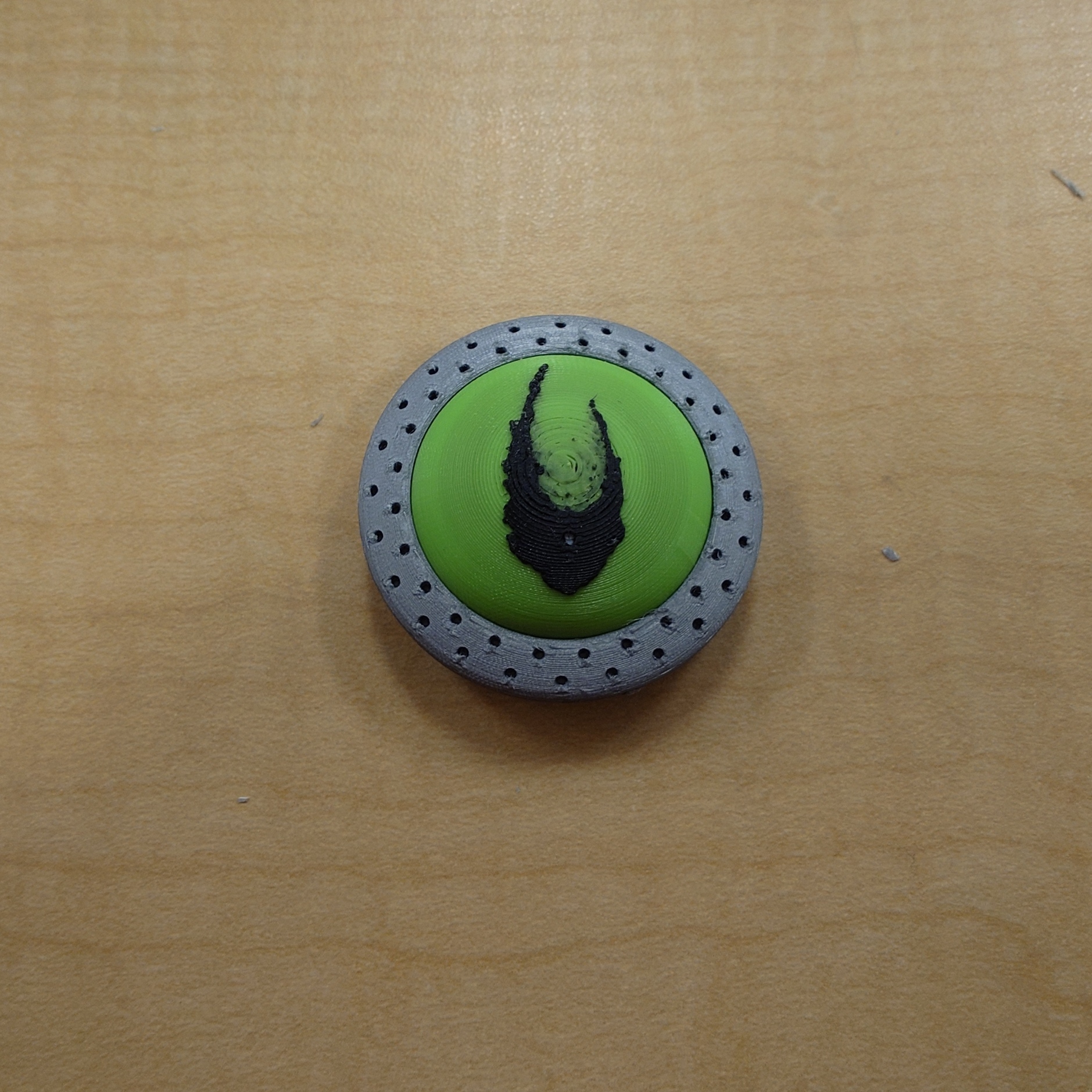
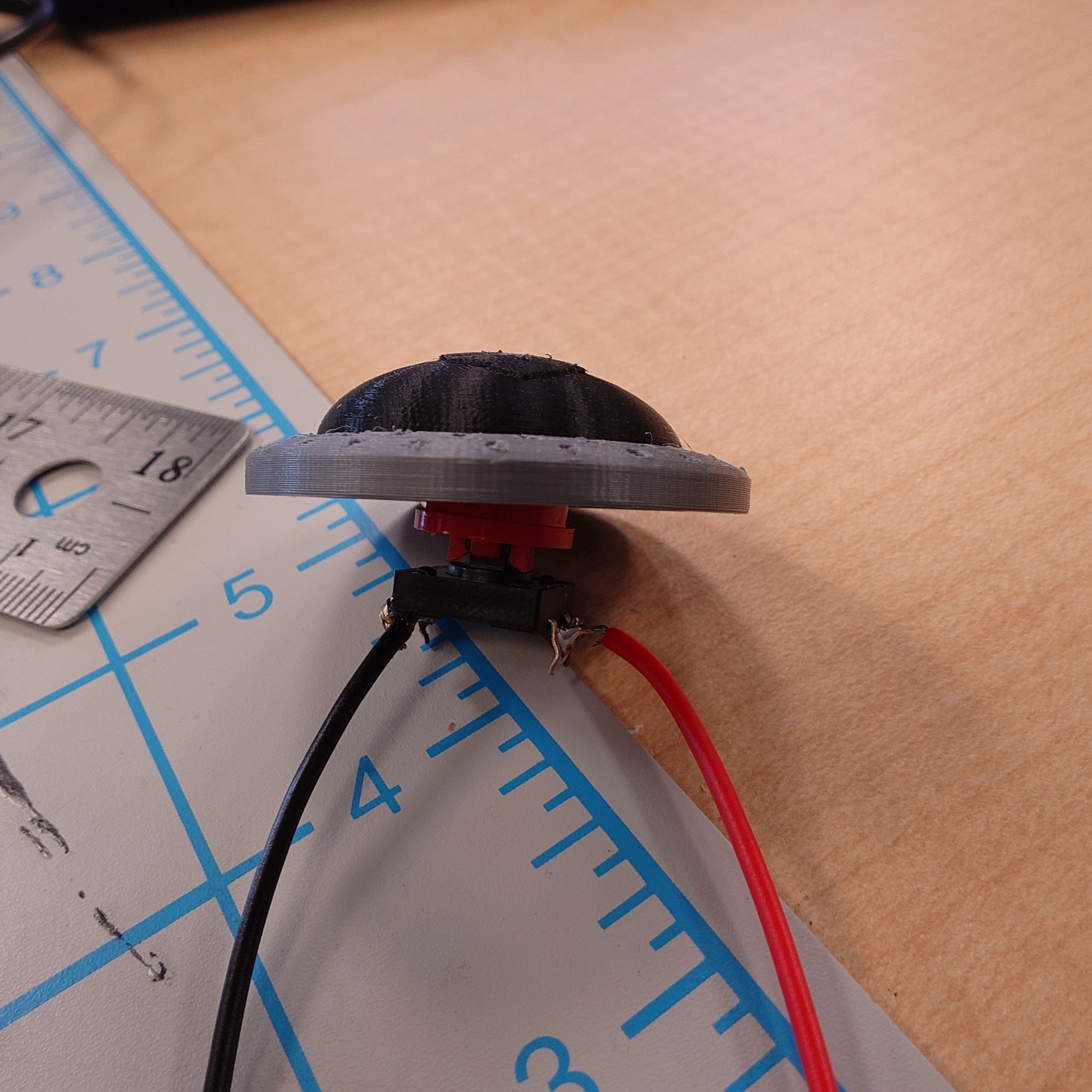
It’s taken me so long to do all of this that my brand new button has been sitting around for a while! It’s time to show it off.
Unfortunately, the process was not perfect for the Voya Nui icon. There is a lot of black mixed into the green in the center, something I cannot clean up at all. The ring also suffered from some very odd issues, probably due to it being so small, and me printing it with a very, very high detail level.
I don’t really want to reprint either of these. They’re not unusable, and trying to print the bubble again is just priming for more headaches and issues. Perhaps if I have extra time. Either way, my measurements were absolutely perfect. So perfect, that I actually cannot remove the button on the backside of the bubble without a tool, and some force.
Thankfully, this is exactly what I wanted, so no issue there.
With the button complete now, there’s only a few more steps left to go.
One Minute to Midnight
However it will have to wait, as I am out of time for this week. I ended up being very busy and did not work on what I wanted to as much as I needed, so I am a bit behind now. But thankfully, not by much.
From here, all that’s left to do is print the decal and stickers, and then I can start putting the Plexiglass on, and making any final touches I need. It’s been a long journey, and I’m ready for it to be over.
That being said though, there are a few things I’d like to do if I have extra time. First, of course, is adding more debris around the base, as it’s much to clean right now, and scattering some extra rocks can really help sell the illusion. I’d also like to secure the platform raisers, as while they will work, they’re very loose right now and don’t sell the idea that this was made by a professional very well. Beyond that, I may reprint the button if I can’t stand it, and I may also end up adding more decals and stickers as I go.
For now though, I need to rest and prepare for my finals next week!
Week 13 has crept up now, leaving only 3 weeks left to complete this project. No time to waste, so let’s get into it.
Fencing Up
Continuing from last week, I immediately got to work making a few more fence sections. Once I was satisfied with the amount, I added them to the display in a way that would help sell the story idea that the Inika were storming the gates of the Piraka Stronghold.
These positions are in no way set in stone, especially because I’ll be removing them shortly to paint over them, but I think it’s a good start.
I also want to add bits of wire strewn about to better show that the fence is supposed to be broken open, but I’ll work on that after painting. Which speaking of…
A Fresh Coat
It’s finally time, at long last.
To get the base set up for painting, I lifted it up using some plastic cups, and removed the cables from each Toa underneath. Then, I removed the fence I just added, and finally, the Toa themselves.
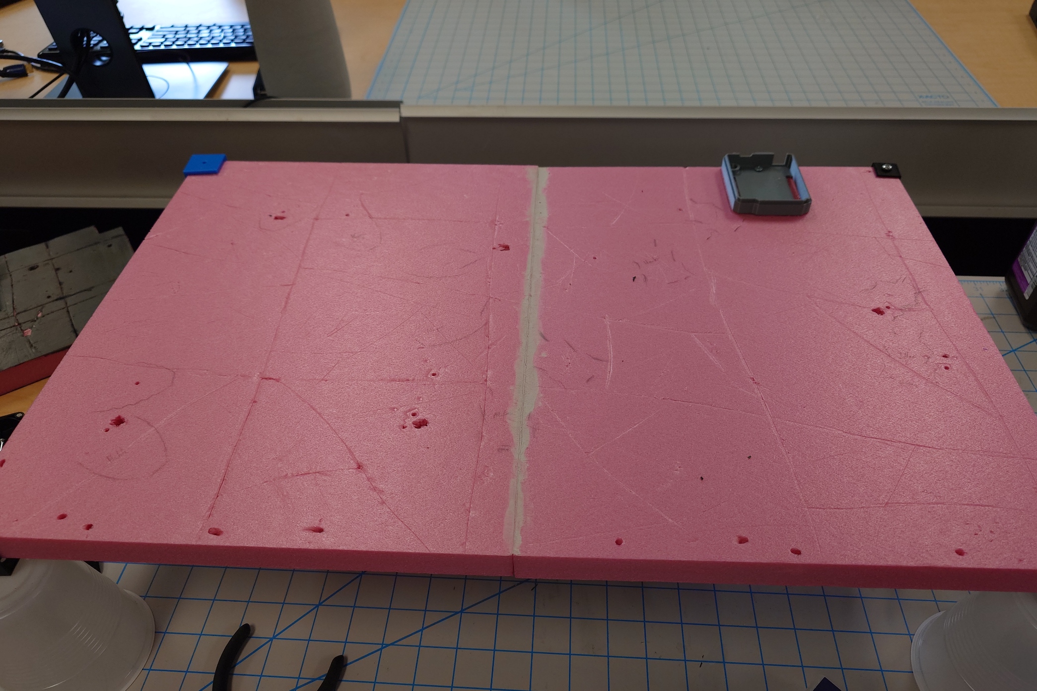
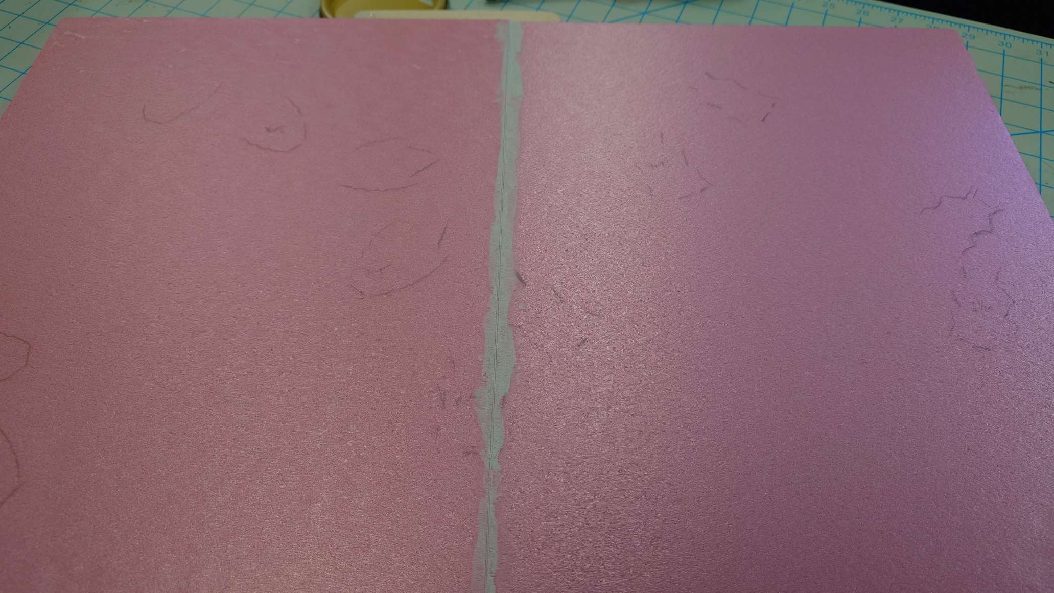
Once that was all done, I scored the board with a knife to mark out the tiles, this time doing it by hand with more room for error, to really make it look like it was natural rock carved by enslaved Matoran.
I also made sure to give plenty of scratches, cracks, and other textures to show wear and tear.
Then, I simply just put a few coats of my primer mixture on it and waited for it to dry.
While waiting for it to dry, I began work on a button design, and I knew exactly what I wanted to do.
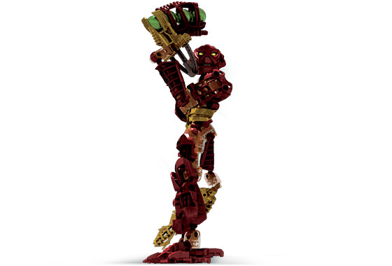
In the image below are some of the icons used to represent the first half of the 2006 year of Bionicle. The one of focus here is the Zamor sphere with the icon of Voya Nui inside of it, surrounded by some metal object.
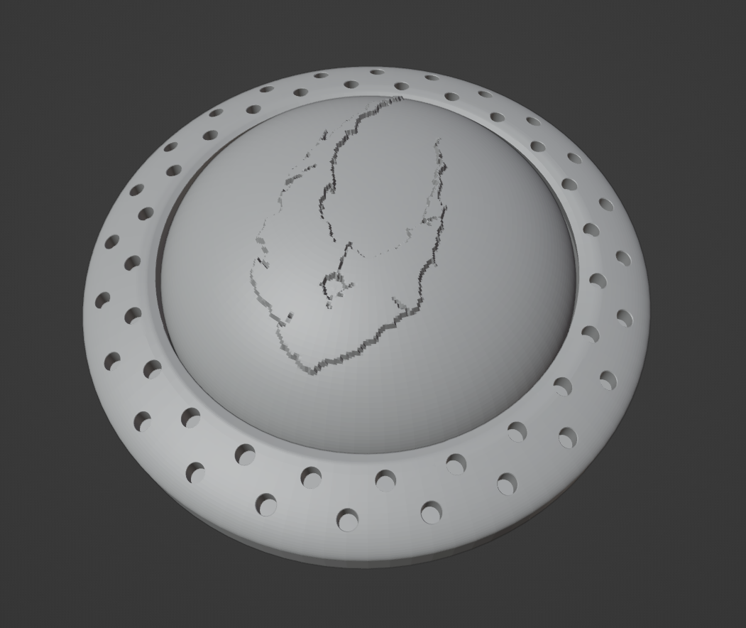
It’s definitely clear by now what my intentions are. I couldn’t help but notice how well it would work as a button, so I got to designing a model for it in Blender.
I worked on it for a bit, but it was quickly back to painting as the layers dried faster and faster.
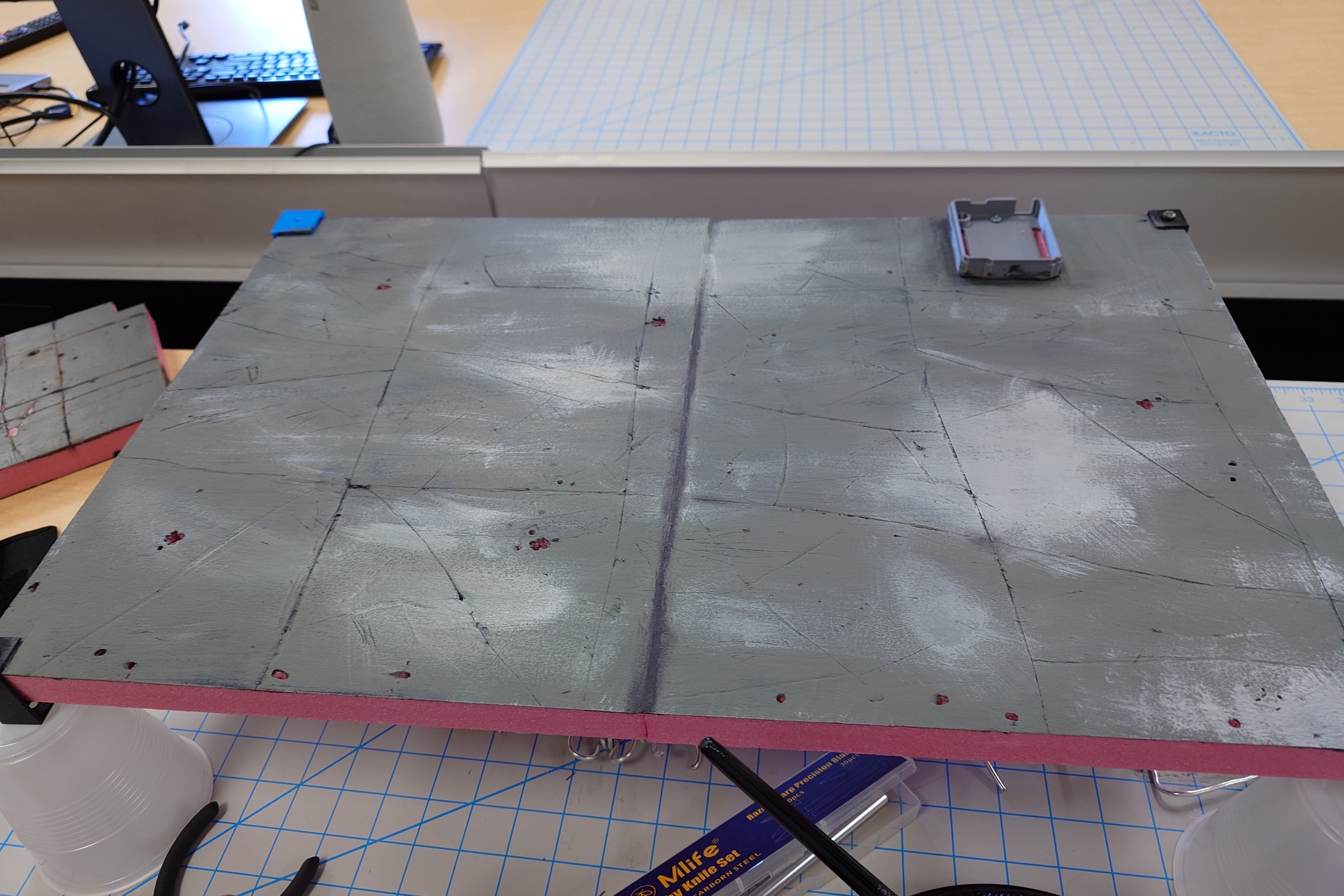
After applying the primer layer, I put a layer of grey over the entire board, and used a lighter gray to try and throw some highlights around it, to spice it up. I don’t think I did very well.
Nonetheless, I’m still satisfied with how it looks so far. The next step will be to apply a very small amount of the brown wash I used previously. I’ll make sure not to go overboard again on accident.
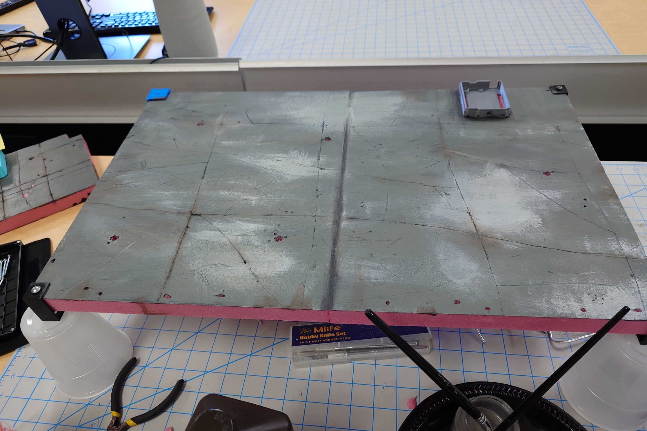
Which I think I did a good job at avoiding.
While I’m overall satisfied with the look of it now, before I seal it in entirely, I want to give it a day for my eyes to rest and refresh. I can always make adjustments now, but once I put the varnish on, that’s it, no more edits, so I want to make sure I have it right.
The Next Day
Coming back to it, I really, really like how it turned out. I did have to go over the lines a bit with a knife to redefine the edges, but I think I did great with this. So on that note, it’s time to seal it up.
I put some layers on, and continued working on the button design while I waited for them to dry.
After some tedious copy and pasting, I came out with this result:
I gave it a test print and I’m mostly satisfied with the result.
I’ll need to make a few tiny adjustments to the size and specifics of it, but the overall core idea is there.
But with that short detour, the base has had enough time to dry fully, so I went ahead and started reattaching the chains and Toa.
While putting them back on though, there was a few things I found I need to address.
Minor Readjustments
First, Jaller desperately needs a coat of nail polish on his joints. He’s flying around like his joints aren’t supposed to stay attached.
The other thing that was bothering me is the composition of the Toa, again. Specifically, I didn’t like how similar of a position all of their swords were, as it became very noticeable with the lights on. It’s too late to change their positioning, but I can at least move their arms.
Specifically, I wanted to change up either Kongu or Matoro, and Nuparu or Hewkii, as the way they hold their swords are much too symmetrical.
For Kongu and Matoro, I decided to adjust Matoro so that his sword was raised up closer to his chest, rather than being parallel with the ground. I may adjust it slightly from here since now he, Jaller, and Hahli are all in sync with a similar pose.
But for now, it will work. Next up I looked at Hewkii and Nuparu. I readjusted Hewkii a little bit, but there wasn’t much else I could do with his current pose, so I had to, unfortunately, give in and allow Nuparu to two-hand his drill again. I just can’t deny that it makes him look so much more dynamic.
Like I mentioned with Matoro, I’ll probably end up making some more adjustments to the Toa, but I don’t think they’ll be worth writing down. But with this out of the way, let’s move on.
Display, to Play-set
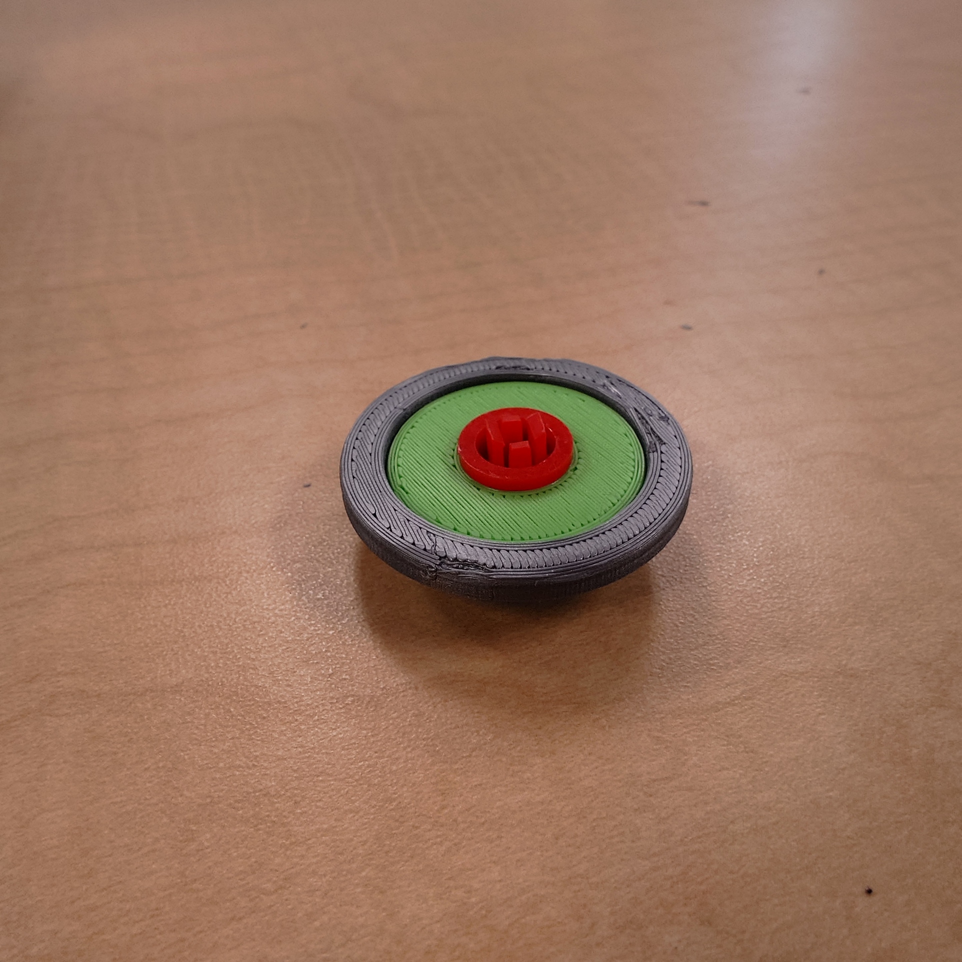
I want to finally get Kongu attached to the display, so I need to work on a button right now. I have the design I want ready to print, but I now need an actual, physical button for my button to press. Thankfully, the DKC has quite a few of those lying around.
I ended up choosing one of the larger buttons with a removeable cap, which means it’ll be easy enough for me to add that into my current design.
Although, it would be much easier to just attach my button to the existing button as is, which is the path I went down. I simply made a hole in the button to fit the other button into.
I still need to widen it a tiny bit, but this will work for the time being, as I am out of time for this week.
End of the Line
There is little time left for this project to reach its conclusion, so it’s a good thing that I also don’t have much left to do. I have received information about the printer I’ll be using, so I can begin work on the decals and get those printed next week, which will leave only the Plexiglass left to assemble. Of course, none of this until I print out the final design for my button.
It has gotten down to the wire, to the point where a single mistake can cause me to not finish the project. Thankfully, as I mentioned before, I will have much more time to work on this during the final week, if needed, but I would rather take the time to relax a bit if I can.
Regardless, I’ll rest up for now and prepare myself to bring this all together next week.
Week 12 at last. Only 4 more weeks to go, and I’m very excited to continue from last week, so let’s get right into it.
Follow the Light
A quick update before anything else though, I plugged Hahli in and left her light on over the weekend to stress test her light to make sure it wouldn’t fail on me at all, and thankfully, the light was just as bright as when I plugged her in. So thankfully, the resistors are doing their job in preventing the LEDs from burning out.
With that being said, let’s continue with the rest of the Toa. I chose Hewkii to be up next, just to work left from right. It took quite a bit of finagling to get the LED block to fit in his axe properly, but I eventually managed to reach a middle ground where, ideally, the LED block will flex into place. I also did a pretty poor job with soldering his cables, making a bit of a mess. But it did work.
Continuing the order from left to right, Matoro is up next.
His sword definitely gave me a bit of trouble, trying to get the wires to fit in. It did also open my eyes to a quite critical flaw in my LED block design. When the block sits on top of the lid, it actually ends up being just very slightly too tall for the battery compartment. This is why I had trouble with Hewkii’s axe as well, and why I had to squish the back plate down for Matoro as well just now.
Since I already have all of the blocks printed, I can’t say it’s worth reprinting them just for a slight height decrease, but if I truly cannot fit the block into one of the Toa’s swords, I’ll consider it.
Regardless, I continued with Matoro and soldered his wires together without incident.
I also found some thin silver wire that was part of some separate LED lights here in the DKC that happened to serve as a great way to replace the jumper cables to tie the lighting cables down to the Toa. From here on out, I used that wire instead of jumper cables.
However, one thing I took noticed of was that I would have a lot of trouble identifying whose cable is whose. I’ve already been using color coordinated cables, but the actual plugs directly underneath the Toa are still black and red, so I quickly just put some masking tape around each cable and wrote the respective Toa’s name on it.
With Matoro done, it’s up next to Nuparu.
His drill was particularly tricky to figure out where to put the holes. The best spot to do so would be on the underside of it, where the handle is, but due to how it’s shaped, his hand takes up the entire spot and leaves no room for cables to be routed. I thought of making holes in the battery compartment, but I’m almost certain that would bring a bunch of unforeseen issues, so I decided against it.
Instead, I opted to put holes on the top of the drill, where they could unfortunately be seen quite easily, but it was the best compromise I could make.
His process went the smoothest of any of the Toa so far, for the most part.
However, I couldn’t help but notice that his light was noticeably dimmer than the rest of the Toa, even compare to Hewkii’s. I believe this is due to me soldering the two red LED resistors on top of each other, and then on top of the power cord. So while Hewkii might only have the effects of one resistor, Nuparu probably is suffering from having the power of two resistors together, making his light dim.
So, I went back to the circuit board and tried to resolder to fix this issue. It took a good minute of reorganizing a ton of wires, but I managed to successfully get everything properly routed.
However, it didn’t seem to make any change in Nuparu’s light, leading me to believe it’s either something about his drill, whether it’s the way it faces or the tube being less transparent than the others, or that it’s the LED itself. Regardless, I want to move on and at least give the light a minute to “warm up”, so to speak, before I decide to replace it or anything.
Kongu would be next, but I want to wait a bit for him, given his unique situation, so I’ll skip ahead to Jaller.
His sword uniquely had an issue where some of the green light leaked through the front side, just above the button. I’ve never noticed this before, and I have no clue if it’s in the OEM light, but either way, I quickly solved the issue by putting some black electrical tape on the problem area.
The rest of the wiring process went fine.
This now leaves just Kongu left. He’s going to be a bit awkward to deal with just because he isn’t screwed in yet, but the process will mostly stay the same.
That being said, his crossbow immediately gave me a few issues. He shares the same problems that Nuparu and Jaller both had, where there isn’t a great spot to drill holes for the wires, and with the light leakage.
Thankfully, because his crossbow handle has a bit more space than Nuparu’s drill did, I was able to drill some holes from the inside of the battery compartment, and route the wires through them. The light leakage problem was also easily solved with black tape again.
After that, it was smooth sailing for the rest of him. Although, I opted to leave his cable dangling for now until I was 100% certain on where his final position would be within the board.
Establishing Boundaries
While I do still need to attach a button to the circuit board, I want to wait on that before working with it. The next thing I want to do is start making the iconic chain-link fence I’ve talked about so much.
For this, I’ll use some armature wire with an appropriate thickness. I don’t really have a plan on what to do beyond that, so I just decided to look at some reference images, and just try my best with it.
Try as I might though, I couldn’t seem to make anything out of it, and it was made very apparent that I had not a single clue of what I was doing. I couldn’t find any guides or tutorials on how to do this online, so I reverted back to asking Chat GPT for advice.
It originally suggested that I try a method of wrapping the wire around an object like a pencil to create a coil of sorts, and then to intertwine the coils together, which would work if I could easily twist the wire. Unfortunately though, it’s just too thick for that, so I had to reconsider.
I tried a few other methods, from trying to create individual loops to link together, to tying zig-zagged pieced of wire together, but every idea suffered from the issue of the wire being too difficult to bend, and even more difficult to bend into even shapes that would properly fit together.
I about gave up for the week, but I decided to ask GPT one more time if it could share some more video guides. While the advice it gave along with the guides didn’t really help me all that much, one of the videos suddenly made everything click.
Specifically, I saw this one by Sofia Bue on YouTube, detailing how to twist armature wire together for clay sculpting. I initially brushed it off since she was using much, much thinner wire than me, but there was one specific part of her method that opened my eyes.
About 40 seconds in or so, she showcases using a drill to twist the wire together, and the way she shows to do it is by taking one long wire that is folded in half on itself, rather than something like two wires put together and twisted at one end.
I very quickly realized that this could work for me as well. While the wire would still take effort to bend into shape, it would be much, much easier to keep the shape even.
I put it into practice, taking one lone strip of wire, folding it in half, making sure to keep a circular shape, and kept twisting it together, creating a general chain-link fence look.
It’s not perfect, but I’m confident it’s the best I’ll be able to get with the tools available to me.
But, once I have one link of the fence, I can modify it to look more damaged and busted by snipping some parts off, and then I can link multiple of these links together using a small piece of wire, which gets me a pretty good look, in my opinion.
It still hurts my hands a ton, even when using pliers to help shape it all, but I’m still glad to have found a solution. I made a few more of these links and set them aside, as I am unfortunately out of time for this week.
Moving Forward
First of all, I apologize for the rather light post this week. I had been very focused on being so hands on with the lights that I somewhat neglected to write this, although I also feel like there wasn’t much to write about, given how repetitive the tasks were.
I was also not a fan of how long it took me to complete the Toa’s lights this week. Due to some personal plans and obligations, I only managed to complete one each day, until Thursday in which I finished up Kongu.
Due to the time it took, I didn’t have enough to spare to work on this armature wire and discover the solution I did, which means I was unable to paint the foam base, so I am unfortunately behind schedule. This is also not to mention that I still need to work on the button function for the lights.
I only have three weeks left to complete this, so I really need to speed things up. Next week, I’ll apply the chain-link fence, and then paint the base after removing the fence and Toa temporarily. While I wait for the layers to dry, I’ll continue to work on a few designs including a button, some way to store the circuit board underneath the display, and some minor changes to the platform raisers on each corner of the base.
Once I have the paint put on, and I’ve printed out my various designs, I’ll shift focus to the Plexiglass and start working out how to apply it to the display. All of this will almost certainly take up the whole week.
But after that, I will also need to start creating the banner decal I want to wrap around the display. Currently, I’m still waiting to hear back from one group on campus who has a viable printer that I may be able to use. I must find the measurements before going all in on a design.
Ideally, this will be done in two weeks, but I am fully expecting that to just be blind optimism, given how there’s definitely so many other issues that will, without question, show up while getting all this done. I will just have to see.
Week 11 already. As I suspected, the last two weeks went by extremely quickly, so I expect the next two weeks to be slower, which is good as I have some of the biggest pieces of work to do here.
My supplies still haven’t arrived yet, but I expect to have access to them within the week. In the meantime, though, I am limited as to what I can work on.
Back to Base-ics
Have I used this chapter title already? I don’t think so, but I also don’t want to bother looking back at my posts to find out.
Regardless, I let the painted foam sit for a while, but I still wasn’t happy with how it was looking, so I got Shannon and Cartland’s thoughts on it.
From my discussions with them, I decided that for the real display, I’ll make a couple of changes to my strategy. Firstly, I’m definitely toning down the brown wash, as I previously stated I would do. Carland specifically mentioned that my base reminded him of the Fallout games, which is not a bad thing at all, but not what I’m going for, and I believe that is due both to the heavy brown, and overall dark color scheme. Which brings me to my next change.
I’ll use a mixture of my grey paints to make a grey that’s lighter than what I have now, but not as light as my light grey paint on its own. I think this will help make the platform look less dirty and apocalyptic overall. Plus it also gives me extra room to add some dark grey detailing if I need.
Finally, I’ll also opt to carve the tiles by hand without the use of a ruler. I believe the reason the entire thing looks so off right now is due to the contrast between the super neatly carved tiles, and the extremely dirty paint job on them. My intention is for them to look like rocks, carved by the Matoran that the Piraka enslaved to build their stronghold, but the lines are much too neat to have that effect. So instead of using a ruler and knife, I’ll just use a flat-head screwdriver and some elbow grease.
Alternatively, if I want to keep the straighter and more properly carved look, I could opt for smaller tiles, but I’ll at least see how I feel about the larger tiles first.
Now, as eager as I am to start this now, I must hold off. I need to first get the cables for the Inika’s swords and figure out where I need to create holes for them in the foam. But since I don’t have the cables, the most I can do for now is position the Toa so they are ready to recieve.
Nailing it Down
I grabbed the display base and positioned the Toa on it, following the general pattern that I had established much earlier, but I did apply a few changes:
First, Jaller and Nuparu’s poses got changed slightly. They kept getting knocked over by accident when I would go to grab another material, and I ended up getting some poses I liked.
I switched Kongu and Hewkii’s positions for the sake of composition and color coordination. I have not mentioned this in depth before, but each Toa shares their sword light color with another in pairs. Hewkii and Nuparu have red lights, Matoro and Kongu are blue, and Jaller and Hahli are green. With the composition I had before, Nuparu and Hewkii were very close together, which not only made them blend in with each other because of their dark color schemes, but I also didn’t think that having their two red swords together would look very good.
I also swapped Matoro and Nuparu’s places to keep the light composition spread out.
Lastly, I made some minor adjustments to the overall composition of the team that I will go into more detail with next.
Despite all these photos I’ve taken, my skill to keep subjects centered and light levels balanced is very poor.
I tried to follow the positioning I established earlier, but I ended up needing to move things around a bit. My biggest struggle was keeping the Toa spread out enough so that they had their own space to breathe, while not leaving massive, awkward gaps between them. I think if I had unlimited funds and time, I would widen the XPS boards just slightly which would help greatly. But alas, this is the best I think I can do.
To help guide my placement, I used some bright green slices of a sticky note to act as a stand in for the little name plates I want to add later, my thought being that I should have enough room to clearly see each of the name plates.
I also left some room around the front edge and corners so that I could easily install the chain link fence for added decoration. I expect that I will need to create some extra foam debris to scatter around the area too, but I’ll leave that as a treat for myself if I need a break from any of the other work.
But with everyone generally in place now, I grabbed some screws, and started putting them in place, save for Kongu. Before I get him in place, I need to prepare the board for its final resting place.
Cable Management Simulator
What perfect timing for this too, as my cables and paint varnish have arrived, so I can finally sort this out, finally.
First, I carved holes in the foam for the wires to connect to the board. Then I screwed the bottom of the board case in place to make sure it would be aligned.
The next thing I needed to do was get some experience with the new cable connectors, as they are extraordinarily tiny.
It’s so small that the LED legs barely fit, with a good chunk of elbow grease and even then, only sometimes, in a specific direction.
Unfortunately, it’s too small for me to use, so I need to discuss with Cartland about it. I found replacements that should be closer to the original size, but we’ll have to wait on them.
In the meantime, I figured it would be helpful to start prototyping my final design for the cables. How will I connect them to the Arduino? How will I spread the power out among the Toa evenly? Questions with answers I need to find.
Power Problems
The biggest issue I faced while testing the lights before is that I don’t know how to evenly distribute the power from the Arduino board between them all. It’s a whole complicated system of wattage, voltage, amplitude, and just having a good set up. Since I don’t have the time to take a full class on all of these systems (although I probably should in the future), I relied on an old friend to help me out.
ChatGPT instructed me to use some resistors to regulate the flow of power between all of the lights. Since the red lights use less volts, they apparently have a stronger draw on the overall voltage, if I’m understanding it right. The same applies to the green and blue lights, of course, but to not as strong of a degree. Having resistors in my setup will help limit how much voltage each LED diode takes up, and will also help increase their lifespan and save them from burning out.
I had quite a journey while setting it all up. From digging through thousands of resistors, to burning out some lights, to occasionally blinding myself, and having to worry about limitations I wasn’t even aware of.
For example, I found out that one output pin on an Arduino board has a safe limit of 40mA, but each LED diode draws 20mA alone, or even up to 30mA for green ones, so I needed to split up the power distribution between multiple pins.
It was quite a lot, and too much to go through here, but this is all to say that I spent multiple hours to get this slightly more organized prototype:
Ideally, this same set up should be stable even when I switch to the permanent, longer cables, but we’ll have to see.
I also had it help me set up a button to activate the special flashing sequence I created previously. As much as I would like to show it off here though, adding that gif very nearly killed WordPress last time, so I will hold off until I have time to kill, or something.
The next thing I need to do is translate this prototype into a final design. I unfortunately can’t use the bread board as it is now because it simply just won’t fit within the space underneath the display, so I’ll need to choose something thinner, and also more secure.
The idea I have for this is to use a perfboard again. It will be easy enough to solder wires to it and create a connection between them all, while also keeping it small enough to fit basically wherever I want it to.
I was initially worried about how I was going to secure the cables to the Arduino board, since the jumper cables I’d been using kept getting pulled out at the slightest bit of force, but thankfully, using standard DuPont connectors are secure enough on their own.
With the basics figured out, I got to work designing and putting together my own custom circuit board.
Feeling the Connection
Just in time for this, my new cables arrived (along with the armature wire). I tested them, and thankfully, they fit much, much better than the previous ones, even if they are a bit bigger. These will be much easier to work with.
To double check the fit of them, I went ahead and printed a new LED block, this time in full black with a higher detail level.
While it printed, I did a quick bit of experimentation with the cables. I knew at one point or another, I would need to extend the length of the wire, because there would be at least one Toa that wouldn’t be able to read the circuit board, so I wanted to get some practice with fixing that.
The easiest way to achieve what I want, while keeping it low profile, is to solder cables together. I looked up some tutorials and videos to make sure I was doing it correctly. I decided that I would put two female connectors together, that way I could plug one side into a male connector to get even more length, and to get some use out of the other connectors that came with the cables. After a bit of time, and a handful of nervous patience, I got some nice results:
I plugged the ends of the male connector into the Arduino, and put an LED in the open female connector, and it worked as expected.
Right on time, again, the LED block finished printing. I wanted to use this long cable with it and Matoro’s test sword, but I quickly realized there was no way to run the cables through the holes I already had in the sword, without removing the solder I just applied. I’m glad to have made this mistake, so I know for the future.
Nonetheless, I just fit a different female connector into the block, along with an LED, and then in to the sword. It took a bit of modifications, mainly due to the poor placement of the holes in Matoro’s sword, but it does fit.
So with all of this in play now, I suppose it’s time to finally route these cables into the display.
Strange New Power
Since I have a plan in mind for the circuit board, the easiest thing for me to do will be to set up each Toa’s sword one by one, that way it makes it easier for me to track my progress and what needs to be done.
First up, I decided to start with Hahli. Partially because I have a backup sword on hand for her in case something goes wrong, and partially because her cable will need to be the longest out of all of the Toa.
The first step was to find out where I need to place the holes in her sword to hide them the best. I managed to find a good spot, but I am still incredibly nervous about making holes in the Toa’s swords, but there’s no more running from it.
After a mild panic attack, and a lot of willpower, I managed to get her LED block set up in place, with the wires.
I place her sword back on her hand to see where I wanted to route the cables, but as expected, it’s too short already, so I went ahead and soldered her cabled with another connector, as I had practiced.
It went quickly and turned out well, so the next step was to actually make a hole to turn the cable through. I chose to do it in the gap of Hahli’s foot, since it happened to fit so well. While organizing the cable too, I also decided to take some advice from the Jaller display, and wrap the cables around Hahli’s body, securing them with bread ties (I still don’t know what those are called).
Since I didn’t have any of those ties on me, I opted to use some jumper cables for now to at least get an idea.
This is about as hidden as I’ll be able to get the cables, and I think I did very good with it.
I wanted to quickly test out her lights again, so I plugged the Arduino in place and shoved the circuit board under the display. Unfortunately though, even with the extended cables, Hahli’s cable still cannot reach the circuit board, meaning I will have to solder some more extensions on, which is no big deal.
Once that was taken care of, everything was working exactly as I wanted it to, meaning Hahli has the honor of being the first Toa Inika to have power to her sword.
Weekly Conclusion
And with that, I am way out of time for this week. It went by super quickly, but I managed to get a very important step done. My work here today has set me up to be primed to finish the lights next week. I imagine that will take a day or two.
After I finish the lights and figure out how I will deal with the circuit board, I’ll turn my focus to the top of the board once more and work on the chain link fence, and once that is all set up, I will be ready to finally paint the base of the display, which will then let me move on to applying the Plexiglass.
There’s still lots left to do, so I will rest and recuperate to make sure I’m ready for it all next week.
It’s now week 10, which means there’s only 6 weeks left to go on this semester. Time is quickly running out, so let’s get started.
Tactical Espionage
I want to immediately get started on disguising this Arduino board, since I’m expecting it to be quite a process.
The idea I have right now is to just try and blend the edges of the box with the base of the terrain, so it helps hide the unnatural shape of it. My intention is to make it look like a piece of rubble, possible from the wall of the Piraka stronghold.
While I work on the design for this, I’ll be printing the case again but in a different color that should match the color I’ll paint the foam around it, since the bright blue makes it stick out a bit much. The best color that was available was one just called “Silver”.
With it printing, the first thing I need to do is refine my cutting technique, because, as I said in the last post, I have been unable to get any clean cuts in the foam so far. For this, I just looked it up online. There are a great many guides that suggest using tools that I don’t have access to, such as a hot wire, or jigsaw, but I did find this video on YouTube that shows off how to achieve clean cuts with a utility knife, which I do have access to.
In the video, he suggests using a square to help with getting straight cuts. While I don’t have one as fancy as the one he uses, the DKC did have a smaller one that would get the job done. I followed the technique he used in the video and…
It came out much, much better than any of my other cuts have. It’s not perfectly straight, but that’s fine for my use case. I don’t know any minerals in nature that have perfectly straight edges anyway.
I continued cutting bits of the foam, going nice and slow. It’s a tedious process, but I don’t have any other choice than to put up with it for the sake of quality. I kept at it until I had a bunch of rocky-looking chunks.
I’m quite happy with how these turned out. My process for creating them was to literally just cut the foam down into an appropriately rock-sized chunk, and then just keep cutting in all different directions until I had an appropriately rock-looking rock.
They’ll start really coming together once I paint them, but there’s something to do before that. Something I’ve been especially excited for. To really sell the rocky look, I can put some texture on the foam.
Now, depending on the material that is being created, the texture process will vary quite a bit. But the best way to get a rocky texture?
A bunch of actual rocks! I quite literally went outside with a baggy to the nearest gravel path, and just picked out a few samples (that I will return once I am done).
Now comes the fun part. I put all of the foam rocks into a separate baggy, placed them in a small bin, and then dumped the rocks into the bin with them. Then, I closed the bin and just gave it a good shake. And then after the shake, I took out each of the bigger pieces and patted them down with some of the rocks for some extra texture.
Try as I might, I can’t get the texture to show up on camera, unfortunately, so I won’t bother uploading a photo of the result. I will, however, get a proper photo once I paint the rocks, which is up next.
Edgeification
To paint the rocks, I first coated them with the classic paint and ‘podge primer combo. I went over each rock once or twice with a thin layer, which really helps them look more like rocks.
We’re not done with them though. To help them blend in more with the new silver case, I’ll give a couple of layers of grey paint to each rock once they’ve dried.
While waiting for them to dry, I started work on the platform raiser design I had in mind. It took a bit of work and was a slight hassle, but I came up with this in Blender:
My idea for it is to be a clamp of sorts. The top section has enough room for the foam to slide into (give or take; the thickness of the foam varied by about 2 millimeters), where a bolt will fit through, and then be tightened with a nut. The bottom section gives 15 millimeters of lift, and also has an extra hole so that I can tighten another bolt into the plexiglass that I plan for this to sit on top of.
To make sure it worked properly before going all in on it, I printed a test design of it, which gave me time to focus on the rocks again.
I gave them a coat of grey paint, making sure it wasn’t too dark or bright by mixing the two grey colors I had. While I didn’t intentionally leave the layers very thin, I think doing so helped make them look much better.
I think they could use a bit of extra wear along their edges, but I’m not certain how to go about doing that without exposing the pink foam underneath. So, at least for now, these will do nicely.
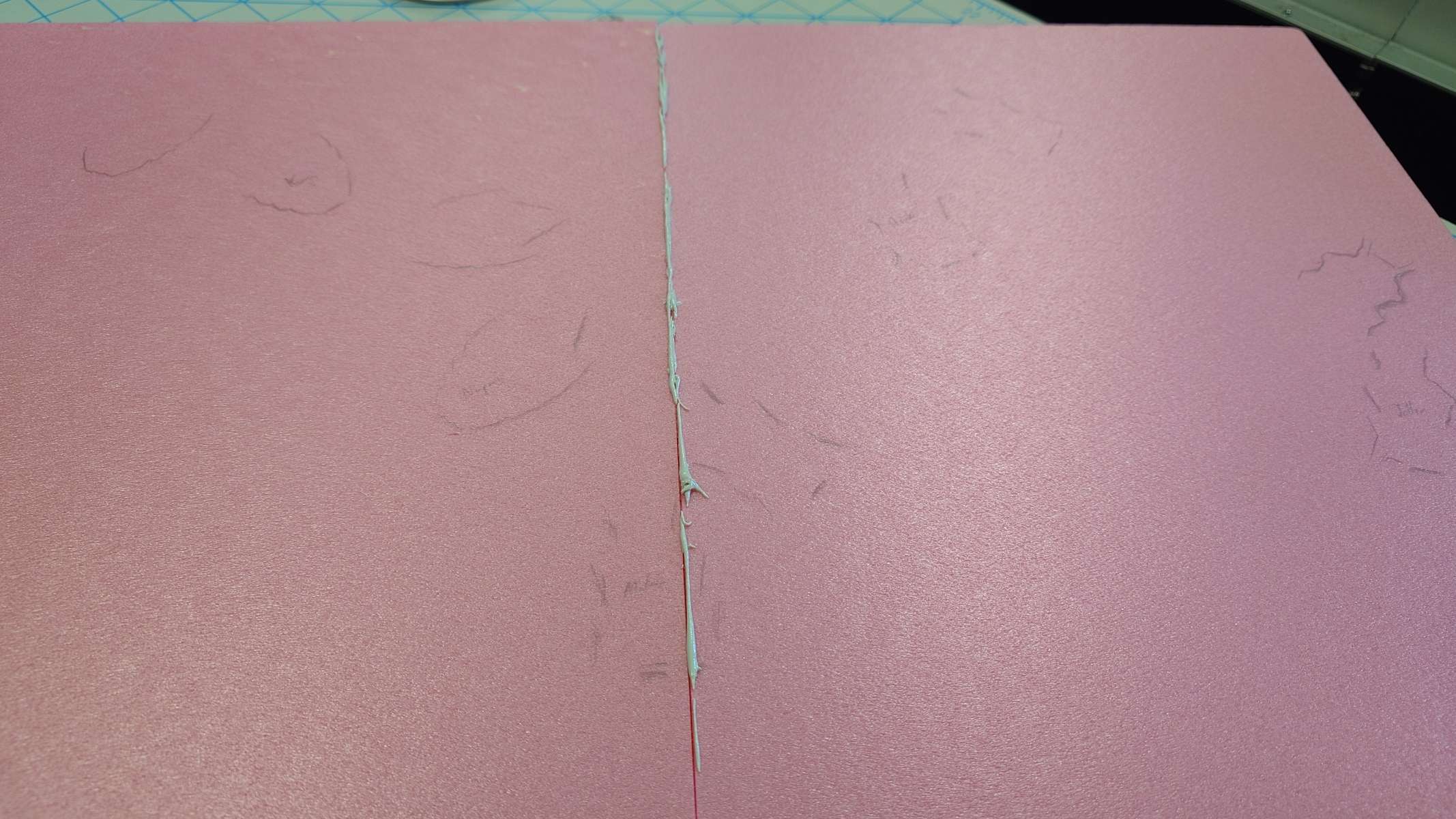
While the rocks are done though, I still want to toy around with painting the base board. I mentioned last week that it was looking a little bland for my tastes, and the first idea I’ve had to fix that is by carving some tiles into it. My thought process is that, because I want the Toa Inika to be storming the Piraka stronghold, it’s not unreasonable to assume there would be some sort of tiled floor.
I started by scoring some shallow lines using a ruler and knife, keeping the tiles generally wide.
From there, I took a random flathead screwdriver and ran it through the lines a few times to roughen the tiles up a bit. After that, I randomly started recklessly using the head to add some more wear and tear to the tiles, and pounded the handle somewhat randomly to add a bit of texture.
I made sure it especially put some extra wear on the corners were four tiles met up, but also tried to keep the distribution of damage somewhat even. I don’t think it was the best job, but the fact that I wouldn’t have painted the foam yet comforts me a bit. I expect that all of the visible foam in the cracks will be hidden by the black primer layer on the final product.
Borrowing again from Adam’s arsenal, I tried applying a brown wash across the tiles to really help add some grime to it all. To make the wash, I simply just took a bit of brown paint and mixed it with the nearest water-like liquid I had on hand, which was the hydrogen peroxide I’ve been using to dissolve the paint off the brush.
I tried keeping a decent balance between having it super watery and not very watery at all.
While it definitely helped a bit, I absolutely overdid it. I ended up not using enough peroxide in my mixture, and used too much of the mixture overall, causing me to have to spread it out a lot more than I intended.
I don’t think it looks bad at all, but it definitely is a lot grimier than I was thinking. I’ll leave it for a while and come back to it after some time has passed and see how I’m feeling about it. If I still don’t like it, I’ll try adding a bit of a light grey wash along some edges and corners to try and balance it out. If I still don’t like that, then I’ll know to use much less of the brown wash in my final product.
While I simmer on it, this gives me the perfect time to focus again on the platform raisers.
Building the tallest tower…
Looking at the printed result, it came out a bit differently than I expected.
I purposely made it thick for the structural stability, but this is much thicker than I was wanting. I also made the bolt hole too small and had to expand it a little bit to be able to fit the bolt through, and even then…
The bolt is too short to reach the other side, and even if it was, I wouldn’t be able to fit a nut in that tiny little space. I had to modify the design.
A little bit of tweaking later, and I got this much nicer looking support:
I made sure to widen the hole and thin the entire piece up overall. It definitely looks a bit nicer, but even with these adjustments, the bolt doesn’t have enough room for a nut underneath.
For this problem, I’m thinking I’ll just find a differently sized bolt, assuming the rest of my design does work. Since I’m fairly confident in it, I went ahead and printed three more of these designs to try out on the real base.
Printing all of the supports out, they do lift the base up enough as I hoped, but there is one issue that has reared its head. Despite the foam being advertised as the same size when purchased, it actually varies very slightly, so two pieces won’t have the exact same measurements. This normally isn’t a problem, but because I’m relying on it to be symmetrical in all spots, I’m subject to it.
In three of the corners, the designs fit generally well, even if I’m still not able to attach a nut to them. One corner is definitely a lot bigger than the rest, but I can at least squeeze it down. The same cannot be said for the last corner that is much smaller than the rest.
I tried my best to add a nut to an extra-long bolt, but no matter what, it didn’t stop the support from being shaky and loose.
I tried every other idea I could think of, between using washers, different sized nuts, and even creating a clamp design, but none of them worked at all. The only idea I have left for now is to just adjust the design I have so that it fits specifically on that corner, but I really don’t want to do that.
For now, I’ll leave it as is and come back to it when it’s time to install the plexiglass, since I still need to account for that no matter what design I go with.
Time’s Up
Unfortunately, I have to leave it all here as that’s all the time I have left for this week. I made some progress, but not as much as I’d like, especially considering that I still don’t like how the painted tiles look still.
My cables are supposed to be coming in any day now, so my first priority will be to get this paint job finished up so I can apply it to the main base and then get the Toa in place and ready to connect to the Arduino.
After that is all done, it will be time to deal with the Plexiglass. I have a plan created, but I still need to make sure it is within budget. This will definitely take me to the end of next week.
But with all that being said, I need to start cleaning up here.
Week 9 now, and I feel like time absolutely flew by last week, which means this week is going to be slower. Or maybe it’ll be two fast weeks in a row, followed by two slow weeks, I suppose we’ll see.
Passing the Time
I still haven’t received the cable connectors or paint varnish I need to continue the main side of the project, so I’ll go on a side quest to deal with another part of the project. I was going to have to get around to this anyway, so it works out.
The first thing I wanted to do from last week was add some support beams to lift the base of the display up. This would give room for both the screws in the Toa Inika’s feet, and a spot to place the Arduino board along with the wires running into it.
I figured the first step should be figuring out how I want to position the Arduino, which isn’t as simple as it seems.
In one pathway, I could keep it on the ground, with the wire outputs facing upwards, but then I would need to find some way to mount it to the ground so it stays in one place. I could 3D print a base, or use pieces of foam, but how would I connect either of those to the rest of the display? I could have a giant plate along the bottom of the display that also contains the stands for the foam in each corner, and then pressure fit the Plexiglass around it, but that would be quite a task to do with how small of a print area the 3D printers in the DKC have. I would have to split the plate up into multiple plates, which then presents the problem, how do I connect those plates together? It ends up being very convoluted.
Alternatively, I could flip the Arduino upside down, which would let me use its mounting holes to screw it into the foam, or into some sort of material between it and the foam, just like the Inika. The only issue this problem presents is the same as the Inika, being the stability of it and the foam. Ultimately, this is definitely the easier option in my head.
My idea is to either keep the board off-center on either the left or right side of the display, of course on the back side of it so that it is hidden away. So I got to testing out the position on the same foam block that Matoro and Nuparu stood on, but I quickly realized another issue.
The lip of the transparent housing around the board has an overhang on the side of the plugs. This gets in the way of both plugs pretty drastically. If left on, it would be incredibly difficult to attach a barrel plug, and would be practically impossible to attach a USB-C cable.
Thankfully, the board is easily removeable from the housing, so it’s no big issue, but I was definitely fond of using the housing if I could. But with it out of the way, there is no further issue.
The next thing I needed to do was measure how much space the board and cables needed. Even though I don’t necessarily know what kind of cables I’ll be using to plug into the board just yet, I opted to use some jumper wires which would provide more than enough space for any other type of cable.
With these in mind, I need at minimum 25.5mm of space between the bottom of the foam floor, and the real floor. It’s quite a large amount of space, so I’ll probably remeasure when I find out what the final cables will look like, but for now this will serve as a fine enough starting point.
I also had the idea of making a custom housing that the board can slide into. My idea is to copy the design of the current housing but remove the entire side with the lip and add additional overhangs around the remaining sides. This way, I can ensure the board is secure, while also making it somewhat easy to access in the event that I need to.
Before going ahead and grabbing measurements though, I opted to find out if there was a preexisting model that I could download to save me some time. While it wasn’t the first result, I found that this model suited my use close enough, I would just need to make some edits to it.
Building a Base 2
I chose to use only the base.stl model as it was closest to what I was aiming for. Before making any substantial edits though, I wanted to see how well the base design worked. I threw the model into Blender, added some mounting holes to the base, and printed the result.
I was fiddling around with it to see how loose it was, and surprisingly, I managed to get the board so that it fit just well enough to where it didn’t come out without some force. Initially, I thought I could just use this design as it.
But after further thought, and realizing I couldn’t get the board to stick like that again, I realized it’s probably for the best to just print the top of the case instead of making my edits. This is partially due to me being worried about potential accidents; if the board falls and hits something hard enough, I can’t guarantee that it won’t break something, so having a case would be some extra peace of mind. The other factor in my decision is due to the way the two plugs are nestled in the case. It’s not very pleasing to the eyes, and again, leaves too much room for error when plugging cables in.
So I printed out the top half of the case. Originally, I thought about making a modification so that the barrel plug was covered up, so that only the USB-C plug could be accessed, but I decided against it in case I ever need the barrel plug. It also saves me some hassle.
Revisiting the Rule of Cool
While waiting for the print to finish, I took another look at the poses I had each Toa in, because I just wasn’t satisfied enough with some of them. I started with Hewkii, since I had found an image of him in a pose that I really liked.
Something about it just caught my eye and spoke to me, although I’m not skilled enough to point out exactly what. It’s just a very satisfying pose.
From drab, to fab.
His old pose was VERY stiff and static now that I look at the comparison on my end, so I’m extra glad to have changed it.
It wasn’t as easy to copy over as I had thought, and while I know that the angle and camera I’m viewing it from makes a difference, I don’t feel I was quite able to capture each bit of the pose from the photo. But there’s still plenty of time to adjust it, so I’m not worried.
The next Toa that really bothers me is Jaller. I feel that his pose is too “elegant” and static, and doesn’t take enough advantage of how weird some of the Bionicle poses can be.
I messed around with him to see if I could make anything click. I thought about reusing his pose from the display tube, but I feel it was a bit too outlandish looking. It also just takes up too much space with how wide his stance is.
I ended up searching for images of him and seeing if I could find something I liked. I knew I wanted to go with some type of pose that displayed his inner Ta-Matoran* strength and courage, but I wanted it to be subtle and not going full into the “action hero main character” type of pose.
*Fun fact! – Elements and Prefixes
I was really desperate to put one of these here again, since it’s been a while from the last time I did one of these. This is quite a long one.
Prefixes in Bionicle refer to a character’s element. This originated with the first six elements using the first two letters of each Toa’s name, such as “Ta” coming from Tahu, “Ko” coming from Kopaka, “Onu” from Onua, and so on. This prefix is used when describing only Matoran and places (eg: Ta-Matoran meaning “Matoran of Fire”, or Ga-Metru meaning the water district of Metru-Nui), with Toa and Turaga simply using the straight English usage such as “Turaga of Earth” and “Toa of Air”.
Beyond the six elements of Fire, Water, Air, Earth, Stone, and Ice (corresponding to the prefix Ta, Ga, Le, Onu, Po, and Ko, respectively), there are also 10 secondary elements that were less common than the primary six. These include Light, Shadow, Sonics, Gravity, Plasma, Magnetism, “The Green” (aka, Plantlife), Lightning, Iron, and Psionics. Their associated prefixes are Av, Kra, De, Ba, Su, Fa, Bo, Vo, Fe, and Ce. These elements were typically seen only as additions to other elements or powers, but could still be the primary element of a creature (Such as with Takanvua being the Toa of Light, Makuta Teridax weilding Shadow, and Toa Jovan being the Toa of Magnetism).
The origins of these prefixes are quite fun, each originating from something in the real world, with the exception of Light and Shadow’s prefixes. “Av” comes from the Mask of Light’s name “Avohkii”, “Kra” comes from the Mask of Shadows “Kraahkan”, “De” is from the word “decibel”, “Ba” from the Greek word “baros” (meaning weight), “Su” from the word “superheated” (associated with plasma), “Fa” from the name of the scientist Michael Faraday (who contributed to the field of electromagnetism), “Bo” from “botany”, “Vo” from “volt”, “Fe” from iron’s chemical symbol, and “Ce” from “cerebrum”.
There’s so much more lore and uses from each of these elements, and I would be here all day writing about all of them. For more information, please see this page on biosector01.
There wasn’t really anything that caught my eye, just browsing on Google and Bing, so I went to BioMediaProject in case they had some extra material I hadn’t seen before. That’s when I saw this:
A render of Jaller, in the exact same pose I have Hahli in currently. I have no clue where this render comes from, and part of me doesn’t even believe its official, but I figured this was honestly the best option I had, again not including the display case pose.
It does cheat a little bit, as a majority of official Inika renders do. The camera is below the floor looking up at him, which makes him look like he’s balancing on one foot, and his sword also seems to go below the floor, but it’s definitely more tame compared to some of the others.
I copied the pose over, but I wasn’t entirely satisfied with the results as it just put his sword out of focus too much which, given how much effort I’ve put into making these swords light up, I definitely didn’t like. So I fumbled around with the pose a bit and came up with this:
(I forgot to take an image before re-posing him, so excuse the lack of a comparison)
I’m not sure why the perspective on my camera looks so off, but I can definitely assure that it looks much better in person. But I do quite like this pose a lot better than what I had before. It’s definitely more inspired by the display case than I had realized while making it, but I think I managed to pull out the good traits while leaving some of the bad traits of that pose behind.
I’m still really happy with Hahli’s pose, and while Kongu needs a bit of tweaking, I’m also still overall happy with his. And Matoro gets the only pass to be the stoic, heroic one of the group. So that just left Nuparu, who I really wanted to overhaul, but there really isn’t much that he can do given his claws, but I really didn’t want to leave him in the basic default pose he’s always in.
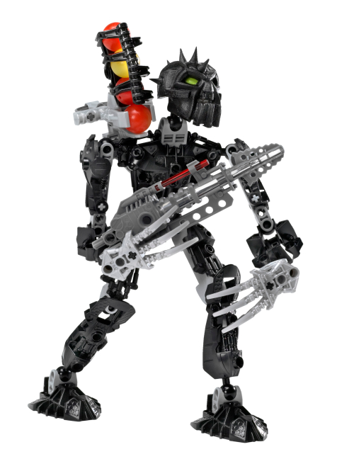
Looking him up, I wasn’t surprised to see almost every picture showcasing him two-handing (two-clawing?) his drill, so I again went to BioMediaProject to find extras, and found these two:
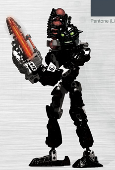
On the left is his stock photo. Every Lego set has one of these, but I’m unsure if they were ever used anywhere outside of the pages on Lego’s website that contain their instructions. But regardless, they clearly are taken by some third-party company, because a lot of them will have weird poses or even completely incorrect features (for example, Jaller’s stock photo shows him with his sword and Zamor launcher on opposite hands, and one of Thok’s photos shows him with his feet on backwards!). That being said though, sometimes that strangeness can be admiring, like in the case of Nuparu here.
Contrasting the real set photographed by people who didn’t understand it very well, is the digital render created by people who definitely had access to a style guide to follow. I’m again not sure where this render is from, or where it was used, but while it does feature Nuparu’s standard two-hand pose, there’s just something about it that makes it stick out from the rest I saw. I partially believe it’s in large part due to the way his eyes glow/shine, but I think having him be in a stance that’s a little more natural also definitely helps. It also only cheats one time, with his left arm being rotated in a way that isn’t possible with the real set.
I had a feeling that the pose on the right wouldn’t really translate well into real life, so I tried copying that first, and as I suspected, the appeal of the render comes in large part due to the way it’s stylized.
So I moved on to the stock photo pose. It definitely looked a little awkward, so I tried just messing around and seeing what I could come up with. I had a lot of trouble finding something for his open hand to do, and also finding a balance between showcasing his drill and his claws.
After a lot of trial and error, I eventually managed to come out with this:
I’m not 100% satisfied with it only because I can’t really explain the “story” of why he hit this pose. Granted, the Rule of Cool overrules this rule, but still, it’s not absolutely perfect.
I think what really makes it hard is that Nuparu suffers from the same issue the future sets from 2009 onwards would face, where his claws give him more of a realistic hand look, which can make unnatural poses look really awkward and noticeable, which isn’t a problem with the standard “hand” that the rest of the Inika have. Oh well.
Back to Business
I’ll let the Toa sit in their new poses for a while so that I can come back to them with fresh eyes and decide if I really like them all.
Now, full disclosure, the posing aspect took much longer than I thought it would, and it is now the next day from when I started printing the top case for the Arduino. This is all to say, the 3D print has finished.
I put the pieces together, and while the case looks and feels nice, the board inside is still entirely loose, which is exactly the problem I was trying to solve.
I solved this problem by attaching a piece of foam on the SPI pins on the back, and also adding the reset button that was provided with the 3D print. I also found some screws to fit on the mounting holes I added.
It’s not perfect, but it should get the job done. I also just really don’t want to reprint the case with a tiny modification.
But with that settled, I can go ahead and get more proper measurements to determine how much space I’ll need underneath. From a somewhat rough use of the micrometer, I came out to about 50 millimeters, which didn’t seem like too much. I attempted to simulate the space by using some wooden blocks that measured out at exactly 50 millimeters, and, well…
It IS a lot, way too much, in fact. Because remember, I have to cover both the foam, and the blocks. Some of that space can definitely be covered by the banner decal that will be wrapped around the display, but the paper for that is already so expensive as is. To cover ALL of this space, I would need to upsize to a massively sized paper, which would just end up making the design look awkward. This is not to mention that I would have all of that extra empty space sitting there for nothing, which makes it a complete waste.
I checked again and again, but I really don’t have the option to attach the Arduino like this, so I’ll need to reevaluate my plan.
The Tinker
I gave myself the requirement of keeping the board/case as hidden and as out of sight as possible, since it would just be lazy to slap it in the corner and call it a day. I know I can do better than that.
I managed to come up with two ideas that met this requirement. The first one I had was to put the board on top, where the Inika are, and disguise it as a stone, or something similar, that Kongu would be stepping on. His pose in the Piraka Online Animations, that I copied, seems to have him standing in such a way, which I think can definitely add to the coolness factor, give a bit of extra depth to the display overall, and help Kongu not get lost in the background.
However, it’s not a perfect solution. The first issue I ran into was figuring out how I was going to manage the cables. To this end, I had two more ideas. Either I can place them upside down and run them underneath the foam through a hole and then back up top into the Inika’s swords. Or, I could keep the board upright and incorporate some way to manage the cables in the design of the board’s disguise. I personally prefer the first method just for its simplicity.
Speaking of the disguise, that brings me to the biggest hurdle with this idea. I’m not entirely sure how I’ll create a design for this that works. Currently, I’m thinking that I can either redesign the 3D printed case for the board, or I can mess around with foam terrain. Both of these will require a lot of work and a lot of time no matter what, so that’s why I came up with a backup plan just in case.
My alternative plan is to keep the Arduino board underneath the foam base like the initial plan, but have it facing upright, and with a hole cut into the foam so that the cables can be plugged into it. This one is definitely less work overall, but it gives less ability to manipulate the cables so that they’re better hidden. I could have the cables run through the foam, but I don’t see any easy way of accomplishing that with my tools.
And just in case neither of these ideas work out, I have a third plan. Borrowing from the display case, I’d keep the Arduino board on the top of the display, and have wires running down behind a background, under the board, and then back up above into the Toa’s swords. The problem with this idea is that it would require fundamental changes to my overall design. First off, to hide the board at the top, I would want to add some sort of lid with a shield, just like the one seen in Jaller’s display, so that it’s not visible, but then that would mean the display couldn’t be viewed from above. It would also require me to add a background, again just like in Jaller’s display. And while I’m not entirely opposed to this, it will drive up costs, and I still don’t necessarily know if that’s what I want yet.
I’m still hesitant to fully dive into any option, so I want to prototype first.
Toiling Away
I chose to give a go at my second idea of putting the board underneath the base. Since the test foam I have already has some holes in it, I just borrowed one to test the idea so I wouldn’t have to worry about making another one.
As I expected though, doing it this way means the cables are very exposed. There may be a way I can blend them in, but it’s going to just be a lot of work that requires a more experienced hand, and a more organized mind, which I don’t possess either of.
So instead, I figured all of that effort would be better spent on creating a disguise.
First, I started with positioning so I could see what the final product might look like.
I’m honestly very happy with how this makes Kongu look. Quite honestly and plainly, it’s just straight awesome. I’m now certain this is the way I want to go, it’s just a matter of making it look good.
I also added some other Toa alongside Kongu, just to see if my theory that this would help him stick out was correct.
It was not, but I believe that’s due to him not actually being raised up at all. This may be a good thing, or I may end up changing it; I’ll see about it eventually.
Fun fact! – Kongu on the big screen
Wow, two fun facts in a single post. I must be spoiling you all.
While all of the Toa Inika made appearances in the first Bionicle movie (Bionicle: Mask of Light) as Matoran, some got more attention than others. Jala was the secondary protagonist, Hahli directly witnessed and chronicled Takanuva’s battle against Makuta, and both of them represented their village in the championship Kohlii match at the beginning of the film, with Huki representing Po-Koro in the match.
This left Kongu, Nuparu, and Matoro out, each of whom, as far as I know, were not seen at all in the movie. However, in the second movie Bionicle 2: Legends of Metru Nui, Kongu not only made a somewhat notable appearance, but also even had a few lines. His only scene was as the Le-Matoran working the chute system, that ran throughout Metru-Nui, being intimidated by Nidhiki and Krekka to reverse the direction of the chutes so the pair could catch the escaping Toa Metru Vakama, Matau, and Nokama.
Measurementing: The Sequel
I gave some more thought to my idea, and I was suddenly hit with a revelation. I had been worried about the wires sticking up out of the board, and while I figured I could hide them well enough in the disguise, I wasn’t sure how it would turn out.
But instead of that, I could essentially combine the two ideas I had by keeping the board above ground in a disguise, but flipping it over and making it so that the cables could go underneath the base, and then run directly to their respective Toa.
This provides two benefits. First, it of course makes hiding the cables much easier, but it also gives some use to the underside of the display, which in turn, will allow me to gather measurements a little bit easier, so I will try this design.
To get a prototype idea, I took the top part of the Arduino case, traced out the holes for the cables, and cut into the foam as best as I could while following the outlines.
It’s extremely messy, both in terms of the final outcome and the process itself. This is something I will need to fix if I plan to create the Arduino disguise out of foam. I’ll do some practice whenever I have a chance.
But, with these holes in the foam, I’m able to easily fit the cables underneath and make a separate hole for wherever they need to come back out of.
Looking at how much the cable droops, I feel that’s a good point of measurement, so I can assume that I only need room for the rest of the cables to be able to move a bit. Going off of this standard, I came out with about 15 millimeters of space; under half of the size of the wooden blocks!
To put it into a visual perspective, I found some rolls of electric tape that measured at 13 millimeters tall, so just slightly below what I want to do, and it looks much more respectable:
It still gives enough space for me to put cables underneath without them being practically glued to the foam, along with some extra leeway in case I find out I need a breadboard for whatever reason. It’ll also be much easier to design a decal strip for this amount of space.
So with that done, I must end the blog post here as I am out of time for this week. It wasn’t a lot of progress, but it was important innovations.
Coming Up Next
Cartland informed me that my materials have been purchased, but I should expect them to arrive the week after the next. This works out fine since I still have some progress to make on the foam side of things.
My plan for next week is to design a supporting beam structure to lift up the foam base. I currently have an idea of what I’m thinking of sketched out already, but I’m sure there’s something important about the design that I’m overlooking. Nonetheless, I’m confident I can finish it next week.
I also will practice more with painting and decorating the base, as the basic grey floor is too boring on its own. To this end, I’m thinking I can borrow some more techniques from Adam on YouTube, and I have some ideas already for what I think might look good.
And then, of course, I’ll need to figure out how I’m going to create this disguise for the Arduino board. I’m really, really not looking forward to this, especially with my extra foam being so limited. I know I can ask Cartland to purchase more, but again, I’m trying to keep costs generally low, again because of the upcoming Plexiglass and paper printing costs.
All of that should keep me more than busy enough to cover next week. But once I have all of those done, the only things left to do will be:
Finalize the ideas for the base paint and decorations
Get the cables attached to the Toa’s swords, and try to keep them organized
Apply both of the above on to the final foam base
Design and print the decals
Apply the Plexiglass
This definitely isn’t a fully comprehensive list, but it still shows that there’s not too much left to do. The hardest parts of this are nearly out of the way. With only 5 weeks left to go though, I definitely want to pick up the pace a bit.
Week 8 now, not counting spring break. This puts us at halfway through the semester. I feel like time has really slowed down now.
Updates
While I usually don’t talk about my personal life in these since it isn’t relevant to the project, I have a few things to bring up from spring break.
First of all, if anyone out there is looking to upgrade or build a new computer, I recommend not buying Nvidia GPU’s unless you have a really good deal on the high-end cards. Nvidia cards have been becoming increasingly overpriced compared to their competition, and their design choices baffle me. I had the cable for the 3090ti break on me because it’s been getting squished in every computer case I’ve had because the 3090ti is already so wide, and the cable just barely fits. And now AMD is producing the 9700xt which has amazing value for its performance.
Amazon also failed to deliver the replacement cable to my address, causing me to hunt it down the entire weekend despite getting overnight shipping, because the replacement wouldn’t arrive until today. Because my computer was out of commission, I ended up playing more of Armored Core 4 on the PlayStation 3, which has been really fun (after I got good at the game).
But besides that, there is one other package that arrived over the break that I have been beyond excited to talk about:
I managed to get my hands on the only Jaller store display I was able to find on the internet. It took some negotiating, some DoorDashing, and a bit of lucky patience, but it is finally in my hands at long last. This means I can now finally figure out how Lego wired up these swords.
The display, despite being in a bit of a broken state, poor Jaller, still lights up even brighter than some of my swords with new batteries in them. Despite my initial assumptions, it uses the same flashing feature as on a normal sword rather than a slow fade in and out, which already tells me that they still use the circuit board in the sword, so I worry that it will just be another case of soldering on to the custom board.
Nevertheless, let’s crack this open and find out for sure.
In The Flesh
Full disclosure, I had already opened this up just beforehand just to make sure I knew how, so the screws are easy to remove now, but they previously required some force.
Taking off the lid, the underside reveals that the button is connected to cables that plug into a cable connector, absolute shocker.
Beyond that, the cable that this connector plugs into runs behind the paper background, but I’m uncertain how to remove it currently (which I will have to figure out to be able to repair Jaller’s head).
Something I’d like to point out is the sheer amount of glue that is on this display. Every single joint, pin, pin hole, axle, axle hole, and even each Zamor sphere are absolutely encased in this stuff, almost to a comedic degree.
As Cartland said, “They really didn’t want this going anywhere!”, which definitely checks out. Between the PET-G plastic casing, the glue everywhere, and the security ties around Jaller’s waist and neck, I have to imagine it wouldn’t even budge even if a kid threw it on the ground and jumped on it like a trampoline.
At least in 2006 anyway. It seems that joints are commonly broken on these displays today, from everything I have seen online. No matter though, this display is safe in my hands now and I will do my best to treat it with the respect it deserves.
I already went through the process of purchasing some replacement parts for both the currently broken joints, and for any other joints that may break during this process. But before tearing any of it off, I would like to find out what type of glue is used on these so that I can find something similar for the replacement.
The glue is oddly springy, transparent, rubbery, and it looks like it flowed very well with how precise some of it fits over these parts. Still though, everyone I have asked so far hasn’t had any clue what it could be. I have a feeling Michael will know though.
Continuing the dismantling process to reach the sword, I took off the bottom cap thinking that it would let me take the plastic barrier around Jaller, but unfortunately, I was wrong.
Jaller, the background, and the plastic are all connected together somehow. I’m still mostly uncertain how, so I continued to take apart what I could.
There are a few things on the back side worth mentioning. First is the clamp that was used to attach the display to store shelves, which is screwed in with a massive flathead screw. Furthermore, there is also two small Philips screws, and what seems to be the security band around Jaller’s waist wrapped around two bolts screwed on by nuts.
I decided to remove the smaller screws first, which, besides making me realize how sharp they were (and putting a few tiny holes in my skin), did a lot of nothing, so I opted to remove the nuts next.
I untied the security cable, which made me a little uncomfortable, but not too worried since it’s the same type of cable used for bread bags. From there, it was as simple as unscrewing the nuts with a wrench. Unfortunately, this also led to nothing.
So I decided to try removing the clamp, thinking that it was hiding some other screws behind it. I was able to take off the bottom part just by turning the screw on the bottom, which loosened a nut that was hidden on the top part.
Doing this… also revealed nothing new. I wasn’t really sure where to go from here, so I just tried prying off what I could.
The transparent white piece, that the initial two nuts kept in place, moved a bit but didn’t come off. Although, it does look like it is a separate tube and cap piece, so maybe with some more force it may be persuaded to come apart.
Before trying that though, I tried to see if the entire black strip would budge at all. While it did move in the corners, it does seem the piece is glued on, which makes me hesitant to remove without knowing how I’ll be able to put it back together. I’ll see what Michael has to say regarding this.
It looked like my only option was to try taking off the white block from earlier, so I got to work. By twisting and turning while gently holding Jaller and pulling it, it did come out, but not in the way I was hoping.
Instead of just the cap coming off, the entire tube came out. I’m assuming this is going to make it more difficult to put it back in later.
But with it out of the way, Jaller is now much looser, but still held down by the wiring. The wiring goes behind the Inika background, to a space between it and the black strip on the back, so I have no way of taking it out without removing the glue.
Since I won’t have a chance to talk with Michael until tomorrow, and it’ll be even longer until I get the replacement glue, I decided to just try and wrestle Jaller out of the case as best as I can, and open the battery cover from there.
I removed the cable around his waist and pulled his broken neck socket through the cable around it, but I still couldn’t get him out of the case, until I spotted a rather well hidden cable wrapping the wires around his arm.
It was a bit of a pain to get untied at first since I couldn’t find the point where it stuck out, but after some prodding with tweezers, I was able to get it untied and pull Jaller out of the case.
Thankfully, there was no glue on the battery cover screws, so they came out incredibly easily.
At long last, I’m able to pull it off and finally discover how it was done by Lego, and…
It’s… nothing special at all?
It’s literally just the normal component that’s in every standard Inika? That’s it?
I mean, I suppose my guess was correct, but I was really hoping I would be wrong. Learning this discovery has dampened my spirits quite a bit. It’s starting to seem like the best option, or maybe even the only option, will be to solder my cables together. I’ll have to brainstorm incredibly hard to figure out a solution.
But, with this discovery made, I have no more use in tearing this display apart anymore. I’ll work on fixing up Jaller as a side project and keep the progress chronicled on here, but other than noting what glue is used I’m guessing that’s about all there is to this display. Although it will still serve as a good inspiration of what I want my display to look like.
While reassembling the case, I first forgot to put the battery cover back on to the sword, and then had a lot of trouble with the two nuts on the back of the case. I discovered that they were actually attached to Philips-head screws behind the paper background, and I wasn’t able to tighten the nuts back on because the screws became loose. So, I unfortunately had to damage the paper a little bit to fit a screwdriver in and allow me to tighten the nuts on.
Thankfully, the damage is mostly hidden behind Jaller, but I absolutely want to avoid something like this in the future if I can help it.
Besides that, I didn’t have any trouble putting the transparent rod back in, which was good, and the rest of the case was just as easy to put back together as it was to take apart. I’m still not sure what those two smaller screws on the back were used for; they didn’t affect anything coming out, and they screwed back in without any issues, so I know they weren’t just keeping the paper background flattened, or something.
As I said before, I’ll work on repairing this as a side project, and it’ll still be useful to have for references, but I’m still a bit devastated that I wasn’t able to find any more clues on how to tackle the wiring.
Back to the Start
While I was working with the display case, I tried coming up with solutions to my wiring problem, and I did come up with something. I don’t believe it’s a good something, but it’s better than nothing.
Every time I’ve dug around the electronic part boxes in the DKC, there’s been one cable that has caught my eye:
This oddly short cable connector. I’ve seen some that look similar to it, pictured on either side of the connector below, but I’ve been unable to find any similar connector that is as short as it.
I wasn’t really sure how to look it up, so I asked ChatGPT about it.
The AI told me that it’s most likely a modified version of the cable connectors seen above. This would explain why I can’t find one of these length’s out of the box, and why it also has tape, or perhaps a shrink-wrap, around the cables.
With this knowledge, I attempted to try making a modification myself. I took two of the single wire connectors (because I couldn’t find any of the 2 pin ones), wrapped them together in electrical tape, and then just tried cutting them in half with cutting pliers. I then wrapped the cut point in more electrical tape, and was left with this:
It’s not the best, and the terminals inside the plastic housing are trying to fall out, but it should technically work.
I tried to fit it into Matoro’s test sword, but unfortunately the design is still too long, and the tape isn’t flexible enough to fit in, but I also can’t remove any more of the housing or tape since the metal terminals will fall out, so this design does not work.
It seems my best option is to just use one of the basic white 2 pin connectors commonly seen on Amazon, so that’s what I’ll have Cartland buy.
Doing the same thing over and over…
While I await the arrival of the cable connectors, I opted to continue refining the prototype I have now.
I took the only available cable connector here and modified my LED block until it fit properly, giving me this result:
I also switched out the yellow LED that was previously in it to a blue one to match Matoro’s sword. While it looks similar to when it had the yellow LED, there are two key changes.
First, I removed a section of the leg splitting bar in the middle. I found that it was incredibly difficult to remove the yellow LED and then insert the blue one because of the bar, plus it also limited the agility of the legs which wasn’t ideal. Going forward, I will incorporate this change into the initial design of the block.
And second, I removed an extra corner by the wires. This was because while trying to fit it into Matoro’s sword, the cables needed a bit of extra space to be flexible enough to bend the way I needed them to. I won’t be able to apply this change to the base model though, since the side the cables run through will change depending on the position of the Toa’s sword. Whatever way will hide the cables the most is the way I’ll orient them.
I also plan to add a proper lid to this design as well. While removing the leg splitter allows the legs to move more freely, it also causes the LED to fall out fairly easily. Adding a lid would solve this problem with no hassle. For the lid, all I need is a 1mm thick plate in the shape of the bottom of the block, with some pins to keep it locked in place, just like the original design.
I printed the design a couple of times and messed around with it, but unfortunately I discovered a few flaws. First, the pins on the LED block itself made the whole thing awkward to print, and no matter which way I did it, the pins never came out round enough to fit into the lid. And the lid itself was too weak, snapping open each time I tried fitting it onto the LED block pins. I also generally struggled to keep the wires contained within the block and sword compartment.
I’m not sure if increasing the internal density of both the block and lid would help, or if I just need to make the pins bigger, but regardless I wanted to take a break from it while I wait for the rest of the cable connectors to arrive.
Back to Base-ics
I wanted to focus again on the base of the display, since I felt a little worried about how little progress I’ve made on it.
I did some painting on a separate piece of XPS foam again just to get more practice with the actual colors, now that I’m more confident in what I need to do for it.
On the underside of the test piece of XPS foam, I coated it in a mixture of Mod Podge and black acrylic paint, painting two layers on it, to act as a primer. It dried super quickly, giving a pretty satisfying result.
There are a few bumps along the surface that I want to avoid when creating the final product, but I’m not entirely sure what’s causing them. My current guess is that it’s just the brush that I’m using. I’ll probably try cleaning it out as thoroughly as I can and hope it helps.
But, continuing onward, I painted a layer of gray over the primer mixture. While the idea I have in mind is to have a metal-like floor, and the gray I’m using is matte, I’m assuming adding a semi-glossy paint varnish will help achieve the look. If not, then I’ll have to order specifically a silver color paint.
While waiting for this layer to dry, I began printing the bolt and nut idea I had from awhile back, so that I can hopefully ground the Toa without worry. As much as I’d like to use the same technique from the Jaller display case, it unfortunately won’t work too well in my larger case.
Results
The first thing I noticed after it came out was that it’s just a tiny bit small.
The screw does fit within a pin hole, so that unfortunately means I can’t really make this design much bigger, and because of its size, there’s a lot of imperfections on the bolt so that it won’t screw into the block without a lot more effort.
As I was fiddling around with it though, I suddenly realized I’m just trying to do the exact same thing as seen on Jaller’s display, just with a different looking nut. So, I went digging for some nuts and bolts.
I also grabbed some basic screws just to see how they would work, and tried them first with Matoro.
Which worked surprisingly well. I’m still a little worried about the long-term stability of this solution, but I’m thinking that I can place a block of wood, or something of similar material, underneath the foam for the nails to dig into. I’ll only do that if I feel like I really need to though, as getting nails of appropriate length, along with specific sizes of some material to screw into will be annoying to deal with.
But regardless, I did the same with Nuparu just to try the method with his feet. While the pins in his feet are a bit more troublesome to access, the technique works just as well.
This now means we have a solution for both the anchoring problem and the wiring problem. The only thing left to do is practice hiding the wiring around the Toa and running it through the foam to connect to the Arduino board. One I’m confident in doing so, I’ll be ready to start putting this thing together.
And since I can’t move forward without those cable connectors, this will be a good stopping point for the week. I really feel like I’m heading towards a conclusion with this project, even if there’s still so much left to do.
I’m still incredibly worried about the Plexiglass casing, and I can’t even say “I’ll worry about it when the time comes” because that time is coming up very soon. I imagine I will be dealing with it in no more than three weeks. And beyond that, there’s still the issue of the printed graphics and such, which will come up just as fast as the Plexiglass.
But there’s nothing I can do about it right now except get some rest and prepare for the upcoming challenge.
Week 7 now, hopefully it’s a little more organized than last week went.
Painting Update, again
Starting off this post, I’m happy to report that the acrylic paint I applied from last week has dried fully and successfully.
The gray acrylic paint is as dry as the brown oil paint is, in only a fraction of the time.
Of course, I need to thicken it quite a bit so that the streaks and primer aren’t visible, but this is good knowledge to have.
Furthermore, I have found that it is best to paint on the mod podge primer instead of just straight black paint or on to the board directly. The primer is effective in keeping the paint stuck on, and it doesn’t rub off on to my finger like the other two applications do.
I’ll apply some extra layers and see how it turns out, but we finally have a conclusion on this saga in sight.
Mind the Gap
Keeping to the theme of the XPS boards, something I failed to do last week was apply hole filler to the gap of the display board, which I will remedy now.
The seam is a lot smaller than I remember it being, and the hole filler putty I have is meant for much larger holes, but I’ll make it work. I opted to use the tip of a skewer to dip into the putty and fill the crack.
I had some trouble getting the putty to come off the skewer and stick to the foam, but a little bit of persistence changed that up. I also came to the realization that the putty wasn’t just going to fall into the seam on its own, so I opted to place some “little wormy dealies”, as Adam so lovingly refers to them as, along it, and then smoosh it down with another popsicle stick.
While it and the paint dry and set, I’ll do some more digging into cable connectors.
Forming a Connection
After multiple hours of research, chatting with ChatGPT, more research, daydreaming, and finally some experimentation, I discovered that the best option I have, if I don’t want to solder wires together directly, is to readjust my LED block design.
The problem I was facing is just the lack of space to work with. Without any changes, my only option is to have items be custom made for my needs, which I want to avoid. Thus meaning, I have to make some fundamental changes.
While throwing ideas at the wall, I ended up forming the idea of turning the LED on its side so its legs are facing to the left or right of the block, when looking from up top. This would then let me fit a basic 2 pin connector in the empty space.
A very rough prototype
To accommodate for the changes made in my prototype, I switched the LED leg separator to be on its side rather than facing upwards, which will give me the freedom to lay the LED on its side, while still being supported from underneath, and hopefully also keeping the legs from crossing over each other.
I also added a base to one side of the empty compartment so that I can create gaps in the sides of it without compromising the structural integrity of the block.
I’ll need to make some more tweaks, but a fuller prototype looks as such:
I opted to use a yellow LED since I was worried about running out of other colors
I worked to try and fit this contraption into Matoro’s empty sword, but I had some serious design flaws that stopped me. Notably, I had trouble getting the LED to stay connected to the connector while I was fitting it into the sword.
It frustrated me a great deal, so I opted to take a break from it for a bit. I have something cooking up in the background that will hopefully solve all of my problems here, but I’ll wait until I have tangible results to announce that.
Based? Based on what?
To pass the time, I decided to move back to the display base. I originally intended to paint it now, but I realized it would probably be a better idea to figure out how I’m going to keep the Toa positioned on it before that.
I brainstormed ideas for a bit, and I figured it would be easiest to make use of the pin holes that are on the Toa’s feet already. I came up with the idea of having a custom printed pin with a stopper on top of it that would connect through the foot and into a Lego pin connector that is under, or within, the foam. I also thought of making a web of Technic rods underneath the foam that the Toa would connect into, but I don’t believe it would be very stable.
I continued on the pin stopper idea and eventually thought of a design that was literally just a normal screw, which gave me the brilliant idea to try drilling a screw in. Attempting this with the small screws from the sword’s battery cover yielded acceptable results… Until I gave the slightest bit of tugging which ripped the screws out, as I expected.
To remedy this, I thought back to my small experience with theater set creation and home improvement. When you want to hang something up by means of screws in a wall, you either check to make sure you’re drilling into a stud, or you use an anchor.
I searched up to see if there were any screw anchors I could 3D print, but while browsing through them I suddenly thought of an alternative idea on how to keep the Toa in place.
Anyone who has bought a Figma or Nendoroid before will be familiar with the idea of having a transparent stand that connects to the figure to keep them from falling over. I thought about trying this idea, but I realized very quickly that it still leaves me with the same problem. How do I stabilize the stand? Screwing it in seems to be the only option.
So I continued looking for information about anchors.
That Ship Sailed
I searched to see if anyone had tried putting anchors in foam before, and I came across one blog post where someone was asking about just that. Unfortunately, most of the responses said that it just isn’t going to work, because foam doesn’t have enough structural integrity to keep even the anchors in place.
So it was back to brainstorming. Keeping with the screw idea, I came up with using a bolt and nut style design. My idea is to have bolts that run through the pin holes on the Inika’s feet that will then screw into a nut embedded into a plate underneath the foam.
My thought process for putting the nut into a larger plate is that it’ll add more surface area to prevent the nut from tearing a hole straight through the foam. Furthermore, I’m thinking that I can embed the nut design into a larger plastic plate so that there’s even less of a chance it’ll damage the foam. But before that, we need to try a prototype to make sure the idea works at all.
I used a free nut and bolt model and made the necessary modifications to each of them in Blender.
I ran out of time for this week, quite suddenly, might I add. Next week is Spring Break so it’ll actually be two weeks before I return to this project again. I’m looking forward to the refresh.
Kicking off week 6, I did not manage to get acrylic paint over the weekend, so I will have Cartland order some off Amazon, where it will hopefully arrive quickly.
I don’t have anything witty to say while writing this, so let’s just get right into business.
Solving the Enigma
Because there is still some time before I can print on the 3D printer today, and because I can’t paint the base like I intended, I decided to look into the cabling process again, since I will need to figure out how to run these cables to the LED lights soon.
I just decided to look at the official Toa Jaller tube display, to get some ideas.
I initially was having trouble finding some pictures of it that showed more than the front-side view, but eventually I ran into this amazing video on YouTube that goes into a lot more detail for the tube:
At around the 3:46 timestamp, the reviewer provides this perfect, fantastic shot which shows off the wiring:
From the frame, we can see that Lego made some small holes at the base of the sword, just large enough to run some wiring through. This process proves to me that I won’t really have another option other than to make holes of my own on my swords, so I will need to find the proper tool to do so.
Furthermore, I also reached out to the Instagram account bionicle_sealed_history to ask if he had any more information on these displays. While he didn’t know specifically how the cables were run through the sword, he did inform me of some very important details.
For one, I was made aware of a larger Inika display that shows off Jaller, Matoro, Nuparu, Hahli, and the Piraka Vezon and his cursed Fenrakk. While I knew that there were other Inika displays like this, this one specifically had a light up function for the Toa which I did not see in any other Inika displays (it was also seemingly triggered by motion!).
Fun fact – Vezon and Fenrakk
Story spoilers for Bionicle 2006 in this fact! I’ve tried to keep spoilers light for any of those who are interested in tackling Bionicle’s story in chronological order, but this will be an exception because I have the urge to write one of these facts.
Vezon (pronounced “vey-zon” and not “vee-zon”) was the secret seventh Piraka, created after Hakann used the Spear of Fusion on Vezok (also pronounced “vey-zok”), causing him to split into two. Vezon was (somehow) more insane than Vezok, and would eventually betray the Piraka to try and beat them to finding the Mask of Life on Voya Nui.
While the Piraka, and subsequently the Toa Inika (and most likely also Toa Jovan’s team), had to face multiple trial chambers on the path to reach the Mask of Life, Vezon was allowed to freely pass all of them and take the Mask of Life.
However, the Mask had tricked him into becoming a guardian for itself. Instead of granting its powers to Vezon, like it would with a being who was destined to wear it, it fused itself to his head and became chained to an enlarged Fenrakk spider, cursed to be a guardian of the mask and never leave the Chamber of Life.
On top of this, I was told the following regarding both the larger display and the Jaller tube:
“The cable was routed along the arm to the back of the Toa. In the case of the small display, the cables were routed underneath the background paper. For the large display, the cables were routed through the Toa’s leg and under the base.”
While I’m unable to spot the cables in the image due to Instagram’s horrible compression methods (which is probably a good sign?), I at least have a good enough of an idea to figure out how to set up the cables for myself; the specifics of which I will figure out once I reach that step.
But first, I need a drill, and a very, very tiny drill bit.
A slight aside
Further regarding the display case shown above, it also provides a good example of what I’m wanting my final product to look like. Notably, I’ll be reusing the paper background and the small set information displays at the base of each Toa (and Vezon).
I plan to have the chain-link fence around the edges of the display by using armature wire, as previously mentioned in another blog post, and I plan to have a strip of paper running around the bottom. In the case of this display, this strip only has the Lego logo and a hand motion icon, but I have some ideas to make mine stick out a lot more.
I also particularly like the addition of the Inika logo on the top left, so maybe I’ll consider adding it on to my display. I’ll see how I’m feeling.
Checking up on a friend
I still have some time before I’m able to use the 3D printer, so I decided to check in on the XPS boards I had glued together a couple of weeks ago, because I just realized that I hadn’t done that.
They seem to have set well enough. They feel sturdy, but I wouldn’t be comfortable with applying a ton of force to them. The seam in the middle is bothering me quite a bit though, but I can figure out how to seal it up.
I went back to check North of the Border for some references, because I remember that he has a certain way of creating mud for his displays, and I planned to use whatever mixture he uses to fill in this seam.
Luckily for me, he just recently created a creative display featuring the popular Moo Deng (my beloved) and another pygmy hippo battling it out on an outdoor terrain.
While creating the base for Moo Deng, instead of using his typical combination of Mod Podge and some other items, he just used hole filler to create the mud. It’s so simple, it’s genius. So I now will buy myself some hole filler to seal the gap between my boards (and also to just have on hand).
Also, while I was scrolling through the video to see the mud process, I spotted Adam using the exact kind of drill I was thinking of using for the Inika swords. I suppose I had just forgotten I got that from him. I checked the description to see if he linked the exact drill he used, but no luck. I assume it doesn’t really matter which one I use though.
Fun fact! – Moo Deng’s name
Moo Deng is a pygmy hippo in Thailand, and as such her name is of Thai origin, with “deng” meaning “(to) bounce or spring”, and “moo” just meaning pork. So Moo Deng quite literally means “bouncy pork”!
Looking Out for the Little Guy
At long last I have the 3D printer available. I immediately put my sliced LED block model to print. Thankfully because it’s so small, it doesn’t take very long at all, even at the highest quality. This will be crucial for making the most of my time.
After a short time, I got this result:
Not bad for a first draft, but it definitely can be improved upon. The studs on my block are a little bit taller than the original, and seem to be just barely thinner in diameter. The LED slot is also too thin to fit an LED in without some damage. As for how it fits in the sword…
As they say: “Like a glove”. This surprised even me, as I fully expected to have more than a few measurements off by just enough to make a difference, but even the clips I designed are doing very well at their job.
There’s even enough extra room for a circuit board between the block and battery cover!
It isn’t perfect however. Like I said, I’ll need to readjust the tube where the LED will slot in, because even putting some force on the LED doesn’t make it slot in very well, and it also expands the plastic, meaning the block won’t fit in the sword as is.
I’m also thinking about making the battery compartment on the block hollow. Right now I just have it filled in completely solid, but hollowing it out will both reduce the print time even further, and also allow me to fit the cables in.
I applied these adjustments to the model in Blender to get this:
For the sake of documenting my changes, I hollowed out the battery casing but left a divider so cables would not touch, added a slight curve to the inside of the LED tube by using an elongated sphere to hopefully fit the LED better, and I also added a slight bevel to some edges for decoration and for (hopefully) an easier time putting the LED in the block.
These changes only removed a minute of printing time (down from 11), which is less than I hoped, but it’ll probably make a bigger difference with higher qualities.
But, after a few micro adjustments, and a little bit of a printer hiccup, I came out with this:
There’s a tiny bit of wiggle room for the LED, but it’s not noticeable enough to where I can confidently make another adjustment to the sizing, so this is fine enough.
But with that, we can now work on a functioning prototype block.
A Conundrum
I originally thought of using a cut to size perfboard to solder the LED and cables on to, but unfortunately, I discovered that perfboards are about twice as thick as the original circuit board in the sword.
It’s not really possible to cut them in half, or sand them that much, and I can’t afford to change the dimensions on my LED block to accommodate them, so I will have to reconsider my approach.
I tried to find a 1mm thick board online, but they are nearly impossible to obtain. It’s not going to be viable to have a company custom cut them, due to costs and time restrictions.
My next idea was to use connectors of some kind. The thought is that I would plug the LED “legs” into one side, and then have the power wires on the other, with the connector sat in the hollowed area of the block (which would require a redesign). Ideally, this would make it so the LED is secure and also so that it doesn’t have a chance of crossing wires and shorting out, while also making it more replaceable than if I were to solder the LED legs and wire together directly.
I dug around some of the electronic parts bins around the DKC for some ideas. Nothing really clicked for me until I found this beautiful cable:
I’m not entirely sure what it was, but something about this cable spoke to me. I had my doubts that it would just work or that it would hold the LED properly, but sure enough…
It works beautifully. I don’t think I’ve been so glad to be proven wrong.
Following off this success, I had a “eureka” moment while fiddling with the LED block. I removed the divider meant to keep the cables separate, and also created holes so that the legs could stick straight down without curving around anything, which led to this:
I think this is the way to go. It has everything I want, while also having the benefit of not needing to deal with solder. The only issue with this set up currently is that the cable is too large to fit in the sword.
Either of these two types of connectors would be my ideal option, since they only have two pin slots and are a lot smaller, meaning I can fit them in the swords much easier.
I’ll take a look online and see what I can find in terms of these.
Another Distraction
While brainstorming some ideas on how I could get this LED to fit, I ended up playing around with the Arduino coding and made a script to flash the LED in the same exact way as the original circuit boards.
I haven’t mentioned this up to this point, partially because I couldn’t be bothered to record it, but the Inika swords have a specific way of flashing for the extra cool factor, rather than just turning on or turning off.
Below is a video of Hahli’s sword performing this flashing (left), and my custom Arduino program controlling Matoro’s sword (right):
My camera’s framerate was a little low for this, but I can confirm that the lights flash in almost the exact same frequency.
I think this could be a fun addition to add to the final display. The normal state of the lights would be on or off, but I could have an additional, physical, button to cause this flashing. To see all six of the Toa with their swords flashing like this has always been somewhat of a dream of mine anyway.
Adding this as a separate function will require me to learn how to use inputs on the Arduino, but I am very confident it will be of no issue.
A Final Quick Update
The paints and tools I needed arrived on Friday, and despite having enough progress for this week to be satisfied, I decided to at least try on the new paints.
I applied some layers of grey paint on various parts of my test block of XPS foam, making sure that I would be able to see where the paint looked best. I put a layer on the Mod Podge primer, the straight black oil paint primer, and on the foam directly itself.
The oil paint I had applied earlier finally seemed to be dry, but hopefully this new acrylic paint will be fully dry after the weekend so I won’t need to wait weeks before being able to use the foam.
As for my other plans next week… I imagine it will take some time for the cable connectors I pick out to arrive, so in the mean time I’ll start planning how to attach the Toa to the foam board, and how I will hide all of the wiring on the display. I’d like to also start taking a look at how I’ll encase the display, and finally tackle the issue of the Plexiglass problem.
Should I become overwhelmed with that, my backup plan is to start planning out a design for all of the cosmetics I plan to print onto paper, and do research into the paper I’ll need. From my previous findings, this is going to be by far the most expensive part of the project just due to the sheer cost to size ratio of paper.