
Week 9 now, and I feel like time absolutely flew by last week, which means this week is going to be slower. Or maybe it’ll be two fast weeks in a row, followed by two slow weeks, I suppose we’ll see.
Passing the Time
I still haven’t received the cable connectors or paint varnish I need to continue the main side of the project, so I’ll go on a side quest to deal with another part of the project. I was going to have to get around to this anyway, so it works out.
The first thing I wanted to do from last week was add some support beams to lift the base of the display up. This would give room for both the screws in the Toa Inika’s feet, and a spot to place the Arduino board along with the wires running into it.
I figured the first step should be figuring out how I want to position the Arduino, which isn’t as simple as it seems.
In one pathway, I could keep it on the ground, with the wire outputs facing upwards, but then I would need to find some way to mount it to the ground so it stays in one place. I could 3D print a base, or use pieces of foam, but how would I connect either of those to the rest of the display? I could have a giant plate along the bottom of the display that also contains the stands for the foam in each corner, and then pressure fit the Plexiglass around it, but that would be quite a task to do with how small of a print area the 3D printers in the DKC have. I would have to split the plate up into multiple plates, which then presents the problem, how do I connect those plates together? It ends up being very convoluted.
Alternatively, I could flip the Arduino upside down, which would let me use its mounting holes to screw it into the foam, or into some sort of material between it and the foam, just like the Inika. The only issue this problem presents is the same as the Inika, being the stability of it and the foam. Ultimately, this is definitely the easier option in my head.
My idea is to either keep the board off-center on either the left or right side of the display, of course on the back side of it so that it is hidden away. So I got to testing out the position on the same foam block that Matoro and Nuparu stood on, but I quickly realized another issue.

The lip of the transparent housing around the board has an overhang on the side of the plugs. This gets in the way of both plugs pretty drastically. If left on, it would be incredibly difficult to attach a barrel plug, and would be practically impossible to attach a USB-C cable.
Thankfully, the board is easily removeable from the housing, so it’s no big issue, but I was definitely fond of using the housing if I could. But with it out of the way, there is no further issue.
The next thing I needed to do was measure how much space the board and cables needed. Even though I don’t necessarily know what kind of cables I’ll be using to plug into the board just yet, I opted to use some jumper wires which would provide more than enough space for any other type of cable.
With these in mind, I need at minimum 25.5mm of space between the bottom of the foam floor, and the real floor. It’s quite a large amount of space, so I’ll probably remeasure when I find out what the final cables will look like, but for now this will serve as a fine enough starting point.
I also had the idea of making a custom housing that the board can slide into. My idea is to copy the design of the current housing but remove the entire side with the lip and add additional overhangs around the remaining sides. This way, I can ensure the board is secure, while also making it somewhat easy to access in the event that I need to.
Before going ahead and grabbing measurements though, I opted to find out if there was a preexisting model that I could download to save me some time. While it wasn’t the first result, I found that this model suited my use close enough, I would just need to make some edits to it.
Building a Base 2
I chose to use only the base.stl model as it was closest to what I was aiming for. Before making any substantial edits though, I wanted to see how well the base design worked. I threw the model into Blender, added some mounting holes to the base, and printed the result.


I was fiddling around with it to see how loose it was, and surprisingly, I managed to get the board so that it fit just well enough to where it didn’t come out without some force. Initially, I thought I could just use this design as it.
But after further thought, and realizing I couldn’t get the board to stick like that again, I realized it’s probably for the best to just print the top of the case instead of making my edits. This is partially due to me being worried about potential accidents; if the board falls and hits something hard enough, I can’t guarantee that it won’t break something, so having a case would be some extra peace of mind. The other factor in my decision is due to the way the two plugs are nestled in the case. It’s not very pleasing to the eyes, and again, leaves too much room for error when plugging cables in.
So I printed out the top half of the case. Originally, I thought about making a modification so that the barrel plug was covered up, so that only the USB-C plug could be accessed, but I decided against it in case I ever need the barrel plug. It also saves me some hassle.
Revisiting the Rule of Cool
While waiting for the print to finish, I took another look at the poses I had each Toa in, because I just wasn’t satisfied enough with some of them. I started with Hewkii, since I had found an image of him in a pose that I really liked.

Something about it just caught my eye and spoke to me, although I’m not skilled enough to point out exactly what. It’s just a very satisfying pose.
From drab, to fab.
His old pose was VERY stiff and static now that I look at the comparison on my end, so I’m extra glad to have changed it.
It wasn’t as easy to copy over as I had thought, and while I know that the angle and camera I’m viewing it from makes a difference, I don’t feel I was quite able to capture each bit of the pose from the photo. But there’s still plenty of time to adjust it, so I’m not worried.
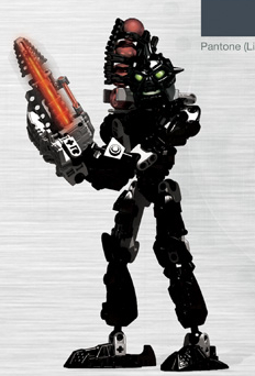
The next Toa that really bothers me is Jaller. I feel that his pose is too “elegant” and static, and doesn’t take enough advantage of how weird some of the Bionicle poses can be.
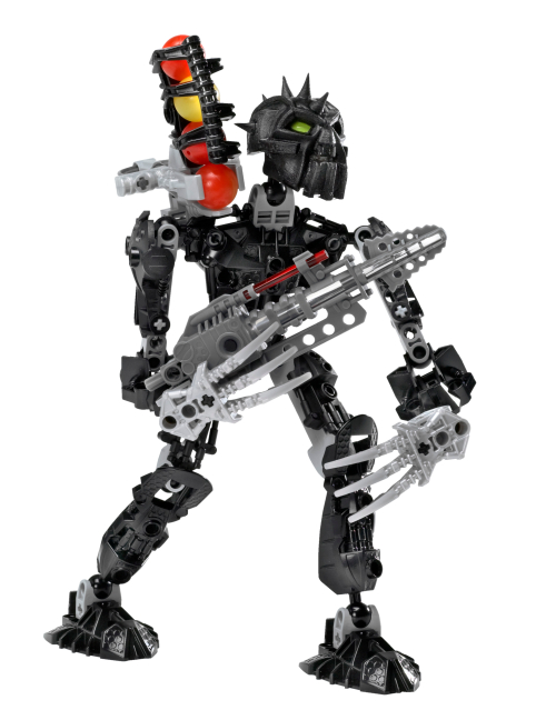
I messed around with him to see if I could make anything click. I thought about reusing his pose from the display tube, but I feel it was a bit too outlandish looking. It also just takes up too much space with how wide his stance is.
I ended up searching for images of him and seeing if I could find something I liked. I knew I wanted to go with some type of pose that displayed his inner Ta-Matoran* strength and courage, but I wanted it to be subtle and not going full into the “action hero main character” type of pose.
*Fun fact! – Elements and Prefixes
I was really desperate to put one of these here again, since it’s been a while from the last time I did one of these. This is quite a long one.
Prefixes in Bionicle refer to a character’s element. This originated with the first six elements using the first two letters of each Toa’s name, such as “Ta” coming from Tahu, “Ko” coming from Kopaka, “Onu” from Onua, and so on. This prefix is used when describing only Matoran and places (eg: Ta-Matoran meaning “Matoran of Fire”, or Ga-Metru meaning the water district of Metru-Nui), with Toa and Turaga simply using the straight English usage such as “Turaga of Earth” and “Toa of Air”.
Beyond the six elements of Fire, Water, Air, Earth, Stone, and Ice (corresponding to the prefix Ta, Ga, Le, Onu, Po, and Ko, respectively), there are also 10 secondary elements that were less common than the primary six. These include Light, Shadow, Sonics, Gravity, Plasma, Magnetism, “The Green” (aka, Plantlife), Lightning, Iron, and Psionics. Their associated prefixes are Av, Kra, De, Ba, Su, Fa, Bo, Vo, Fe, and Ce. These elements were typically seen only as additions to other elements or powers, but could still be the primary element of a creature (Such as with Takanvua being the Toa of Light, Makuta Teridax weilding Shadow, and Toa Jovan being the Toa of Magnetism).
The origins of these prefixes are quite fun, each originating from something in the real world, with the exception of Light and Shadow’s prefixes. “Av” comes from the Mask of Light’s name “Avohkii”, “Kra” comes from the Mask of Shadows “Kraahkan”, “De” is from the word “decibel”, “Ba” from the Greek word “baros” (meaning weight), “Su” from the word “superheated” (associated with plasma), “Fa” from the name of the scientist Michael Faraday (who contributed to the field of electromagnetism), “Bo” from “botany”, “Vo” from “volt”, “Fe” from iron’s chemical symbol, and “Ce” from “cerebrum”.
There’s so much more lore and uses from each of these elements, and I would be here all day writing about all of them. For more information, please see this page on biosector01.
There wasn’t really anything that caught my eye, just browsing on Google and Bing, so I went to BioMediaProject in case they had some extra material I hadn’t seen before. That’s when I saw this:
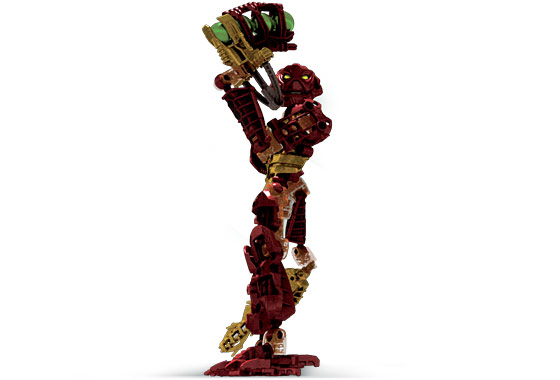
A render of Jaller, in the exact same pose I have Hahli in currently. I have no clue where this render comes from, and part of me doesn’t even believe its official, but I figured this was honestly the best option I had, again not including the display case pose.
It does cheat a little bit, as a majority of official Inika renders do. The camera is below the floor looking up at him, which makes him look like he’s balancing on one foot, and his sword also seems to go below the floor, but it’s definitely more tame compared to some of the others.
I copied the pose over, but I wasn’t entirely satisfied with the results as it just put his sword out of focus too much which, given how much effort I’ve put into making these swords light up, I definitely didn’t like. So I fumbled around with the pose a bit and came up with this:

(I forgot to take an image before re-posing him, so excuse the lack of a comparison)
I’m not sure why the perspective on my camera looks so off, but I can definitely assure that it looks much better in person. But I do quite like this pose a lot better than what I had before. It’s definitely more inspired by the display case than I had realized while making it, but I think I managed to pull out the good traits while leaving some of the bad traits of that pose behind.
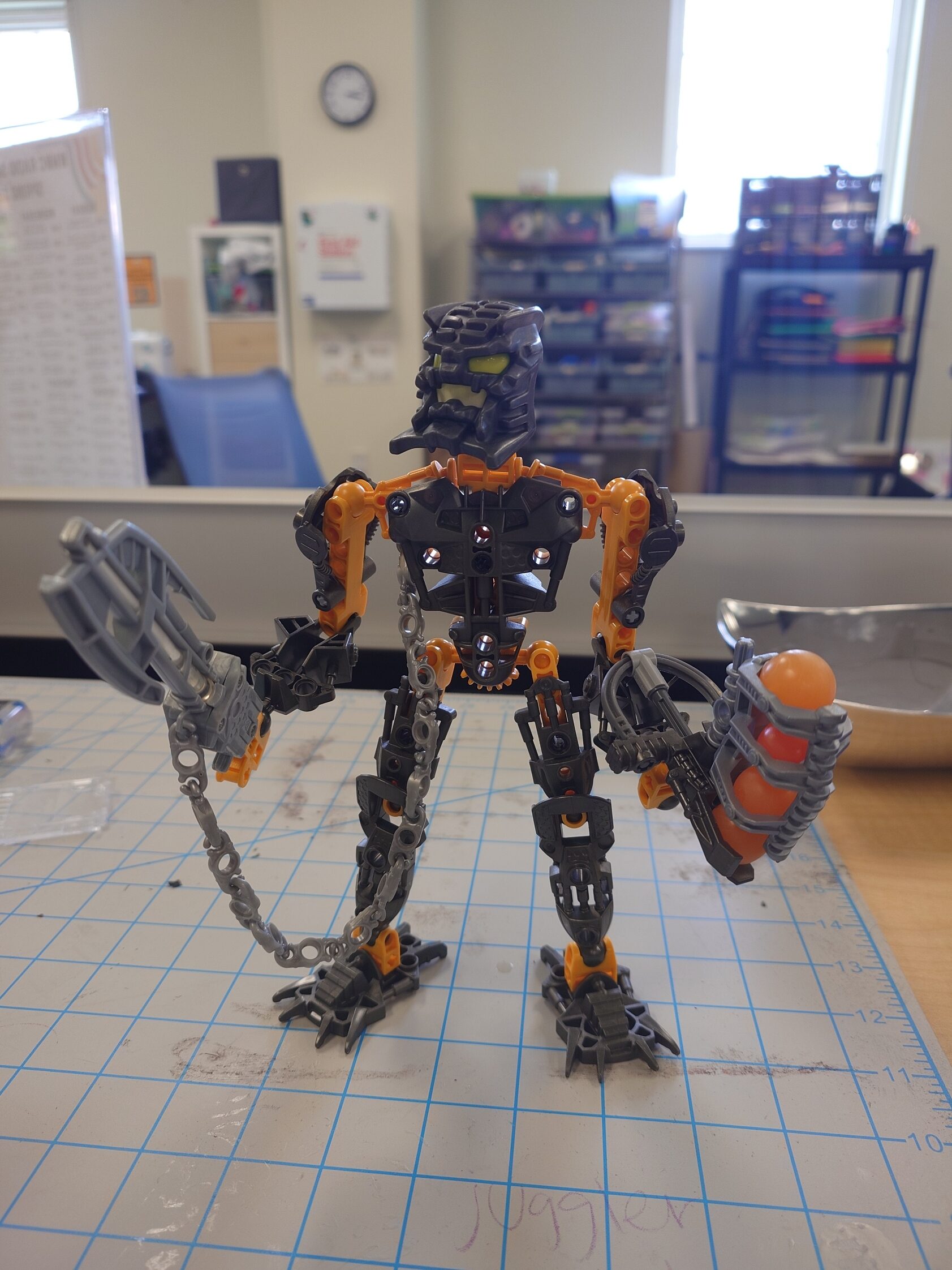
I’m still really happy with Hahli’s pose, and while Kongu needs a bit of tweaking, I’m also still overall happy with his. And Matoro gets the only pass to be the stoic, heroic one of the group. So that just left Nuparu, who I really wanted to overhaul, but there really isn’t much that he can do given his claws, but I really didn’t want to leave him in the basic default pose he’s always in.
Looking him up, I wasn’t surprised to see almost every picture showcasing him two-handing (two-clawing?) his drill, so I again went to BioMediaProject to find extras, and found these two:
On the left is his stock photo. Every Lego set has one of these, but I’m unsure if they were ever used anywhere outside of the pages on Lego’s website that contain their instructions. But regardless, they clearly are taken by some third-party company, because a lot of them will have weird poses or even completely incorrect features (for example, Jaller’s stock photo shows him with his sword and Zamor launcher on opposite hands, and one of Thok’s photos shows him with his feet on backwards!). That being said though, sometimes that strangeness can be admiring, like in the case of Nuparu here.
Contrasting the real set photographed by people who didn’t understand it very well, is the digital render created by people who definitely had access to a style guide to follow. I’m again not sure where this render is from, or where it was used, but while it does feature Nuparu’s standard two-hand pose, there’s just something about it that makes it stick out from the rest I saw. I partially believe it’s in large part due to the way his eyes glow/shine, but I think having him be in a stance that’s a little more natural also definitely helps. It also only cheats one time, with his left arm being rotated in a way that isn’t possible with the real set.
I had a feeling that the pose on the right wouldn’t really translate well into real life, so I tried copying that first, and as I suspected, the appeal of the render comes in large part due to the way it’s stylized.
So I moved on to the stock photo pose. It definitely looked a little awkward, so I tried just messing around and seeing what I could come up with. I had a lot of trouble finding something for his open hand to do, and also finding a balance between showcasing his drill and his claws.
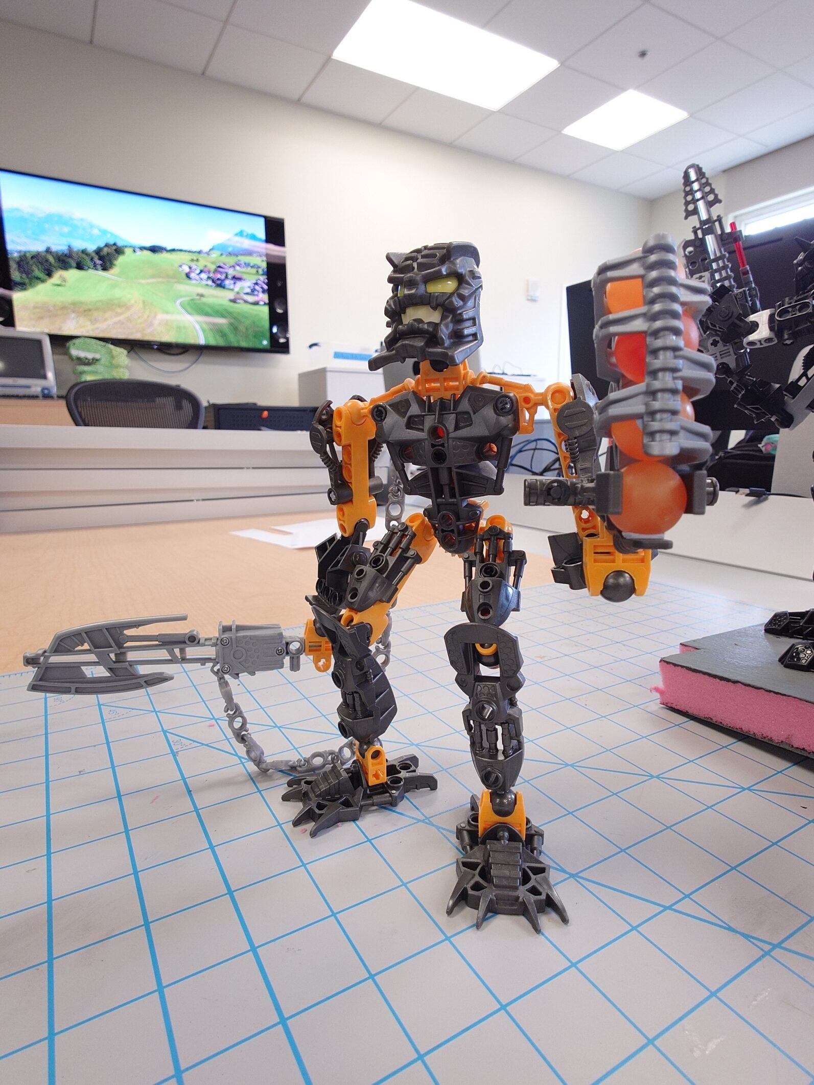
After a lot of trial and error, I eventually managed to come out with this:

I’m not 100% satisfied with it only because I can’t really explain the “story” of why he hit this pose. Granted, the Rule of Cool overrules this rule, but still, it’s not absolutely perfect.
I think what really makes it hard is that Nuparu suffers from the same issue the future sets from 2009 onwards would face, where his claws give him more of a realistic hand look, which can make unnatural poses look really awkward and noticeable, which isn’t a problem with the standard “hand” that the rest of the Inika have. Oh well.
Back to Business
I’ll let the Toa sit in their new poses for a while so that I can come back to them with fresh eyes and decide if I really like them all.
Now, full disclosure, the posing aspect took much longer than I thought it would, and it is now the next day from when I started printing the top case for the Arduino. This is all to say, the 3D print has finished.
I put the pieces together, and while the case looks and feels nice, the board inside is still entirely loose, which is exactly the problem I was trying to solve.


I solved this problem by attaching a piece of foam on the SPI pins on the back, and also adding the reset button that was provided with the 3D print. I also found some screws to fit on the mounting holes I added.


It’s not perfect, but it should get the job done. I also just really don’t want to reprint the case with a tiny modification.
But with that settled, I can go ahead and get more proper measurements to determine how much space I’ll need underneath. From a somewhat rough use of the micrometer, I came out to about 50 millimeters, which didn’t seem like too much. I attempted to simulate the space by using some wooden blocks that measured out at exactly 50 millimeters, and, well…

It IS a lot, way too much, in fact. Because remember, I have to cover both the foam, and the blocks. Some of that space can definitely be covered by the banner decal that will be wrapped around the display, but the paper for that is already so expensive as is. To cover ALL of this space, I would need to upsize to a massively sized paper, which would just end up making the design look awkward. This is not to mention that I would have all of that extra empty space sitting there for nothing, which makes it a complete waste.
I checked again and again, but I really don’t have the option to attach the Arduino like this, so I’ll need to reevaluate my plan.
The Tinker
I gave myself the requirement of keeping the board/case as hidden and as out of sight as possible, since it would just be lazy to slap it in the corner and call it a day. I know I can do better than that.
I managed to come up with two ideas that met this requirement. The first one I had was to put the board on top, where the Inika are, and disguise it as a stone, or something similar, that Kongu would be stepping on. His pose in the Piraka Online Animations, that I copied, seems to have him standing in such a way, which I think can definitely add to the coolness factor, give a bit of extra depth to the display overall, and help Kongu not get lost in the background.
However, it’s not a perfect solution. The first issue I ran into was figuring out how I was going to manage the cables. To this end, I had two more ideas. Either I can place them upside down and run them underneath the foam through a hole and then back up top into the Inika’s swords. Or, I could keep the board upright and incorporate some way to manage the cables in the design of the board’s disguise. I personally prefer the first method just for its simplicity.
Speaking of the disguise, that brings me to the biggest hurdle with this idea. I’m not entirely sure how I’ll create a design for this that works. Currently, I’m thinking that I can either redesign the 3D printed case for the board, or I can mess around with foam terrain. Both of these will require a lot of work and a lot of time no matter what, so that’s why I came up with a backup plan just in case.
My alternative plan is to keep the Arduino board underneath the foam base like the initial plan, but have it facing upright, and with a hole cut into the foam so that the cables can be plugged into it. This one is definitely less work overall, but it gives less ability to manipulate the cables so that they’re better hidden. I could have the cables run through the foam, but I don’t see any easy way of accomplishing that with my tools.
And just in case neither of these ideas work out, I have a third plan. Borrowing from the display case, I’d keep the Arduino board on the top of the display, and have wires running down behind a background, under the board, and then back up above into the Toa’s swords. The problem with this idea is that it would require fundamental changes to my overall design. First off, to hide the board at the top, I would want to add some sort of lid with a shield, just like the one seen in Jaller’s display, so that it’s not visible, but then that would mean the display couldn’t be viewed from above. It would also require me to add a background, again just like in Jaller’s display. And while I’m not entirely opposed to this, it will drive up costs, and I still don’t necessarily know if that’s what I want yet.
I’m still hesitant to fully dive into any option, so I want to prototype first.
Toiling Away
I chose to give a go at my second idea of putting the board underneath the base. Since the test foam I have already has some holes in it, I just borrowed one to test the idea so I wouldn’t have to worry about making another one.
As I expected though, doing it this way means the cables are very exposed. There may be a way I can blend them in, but it’s going to just be a lot of work that requires a more experienced hand, and a more organized mind, which I don’t possess either of.
So instead, I figured all of that effort would be better spent on creating a disguise.
First, I started with positioning so I could see what the final product might look like.

I’m honestly very happy with how this makes Kongu look. Quite honestly and plainly, it’s just straight awesome. I’m now certain this is the way I want to go, it’s just a matter of making it look good.
I also added some other Toa alongside Kongu, just to see if my theory that this would help him stick out was correct.

It was not, but I believe that’s due to him not actually being raised up at all. This may be a good thing, or I may end up changing it; I’ll see about it eventually.
Fun fact! – Kongu on the big screen
Wow, two fun facts in a single post. I must be spoiling you all.
While all of the Toa Inika made appearances in the first Bionicle movie (Bionicle: Mask of Light) as Matoran, some got more attention than others. Jala was the secondary protagonist, Hahli directly witnessed and chronicled Takanuva’s battle against Makuta, and both of them represented their village in the championship Kohlii match at the beginning of the film, with Huki representing Po-Koro in the match.
This left Kongu, Nuparu, and Matoro out, each of whom, as far as I know, were not seen at all in the movie. However, in the second movie Bionicle 2: Legends of Metru Nui, Kongu not only made a somewhat notable appearance, but also even had a few lines. His only scene was as the Le-Matoran working the chute system, that ran throughout Metru-Nui, being intimidated by Nidhiki and Krekka to reverse the direction of the chutes so the pair could catch the escaping Toa Metru Vakama, Matau, and Nokama.
Measurementing: The Sequel
I gave some more thought to my idea, and I was suddenly hit with a revelation. I had been worried about the wires sticking up out of the board, and while I figured I could hide them well enough in the disguise, I wasn’t sure how it would turn out.
But instead of that, I could essentially combine the two ideas I had by keeping the board above ground in a disguise, but flipping it over and making it so that the cables could go underneath the base, and then run directly to their respective Toa.
This provides two benefits. First, it of course makes hiding the cables much easier, but it also gives some use to the underside of the display, which in turn, will allow me to gather measurements a little bit easier, so I will try this design.
To get a prototype idea, I took the top part of the Arduino case, traced out the holes for the cables, and cut into the foam as best as I could while following the outlines.

It’s extremely messy, both in terms of the final outcome and the process itself. This is something I will need to fix if I plan to create the Arduino disguise out of foam. I’ll do some practice whenever I have a chance.
But, with these holes in the foam, I’m able to easily fit the cables underneath and make a separate hole for wherever they need to come back out of.

Looking at how much the cable droops, I feel that’s a good point of measurement, so I can assume that I only need room for the rest of the cables to be able to move a bit. Going off of this standard, I came out with about 15 millimeters of space; under half of the size of the wooden blocks!
To put it into a visual perspective, I found some rolls of electric tape that measured at 13 millimeters tall, so just slightly below what I want to do, and it looks much more respectable:

It still gives enough space for me to put cables underneath without them being practically glued to the foam, along with some extra leeway in case I find out I need a breadboard for whatever reason. It’ll also be much easier to design a decal strip for this amount of space.
So with that done, I must end the blog post here as I am out of time for this week. It wasn’t a lot of progress, but it was important innovations.
Coming Up Next
Cartland informed me that my materials have been purchased, but I should expect them to arrive the week after the next. This works out fine since I still have some progress to make on the foam side of things.
My plan for next week is to design a supporting beam structure to lift up the foam base. I currently have an idea of what I’m thinking of sketched out already, but I’m sure there’s something important about the design that I’m overlooking. Nonetheless, I’m confident I can finish it next week.
I also will practice more with painting and decorating the base, as the basic grey floor is too boring on its own. To this end, I’m thinking I can borrow some more techniques from Adam on YouTube, and I have some ideas already for what I think might look good.
And then, of course, I’ll need to figure out how I’m going to create this disguise for the Arduino board. I’m really, really not looking forward to this, especially with my extra foam being so limited. I know I can ask Cartland to purchase more, but again, I’m trying to keep costs generally low, again because of the upcoming Plexiglass and paper printing costs.
All of that should keep me more than busy enough to cover next week. But once I have all of those done, the only things left to do will be:
- Finalize the ideas for the base paint and decorations
- Get the cables attached to the Toa’s swords, and try to keep them organized
- Apply both of the above on to the final foam base
- Design and print the decals
- Apply the Plexiglass
This definitely isn’t a fully comprehensive list, but it still shows that there’s not too much left to do. The hardest parts of this are nearly out of the way. With only 5 weeks left to go though, I definitely want to pick up the pace a bit.
It’ll all work out, I’m sure of it.