Kicking off week 6, I did not manage to get acrylic paint over the weekend, so I will have Cartland order some off Amazon, where it will hopefully arrive quickly.
I don’t have anything witty to say while writing this, so let’s just get right into business.
Solving the Enigma
Because there is still some time before I can print on the 3D printer today, and because I can’t paint the base like I intended, I decided to look into the cabling process again, since I will need to figure out how to run these cables to the LED lights soon.
I just decided to look at the official Toa Jaller tube display, to get some ideas.
I initially was having trouble finding some pictures of it that showed more than the front-side view, but eventually I ran into this amazing video on YouTube that goes into a lot more detail for the tube:
At around the 3:46 timestamp, the reviewer provides this perfect, fantastic shot which shows off the wiring:

From the frame, we can see that Lego made some small holes at the base of the sword, just large enough to run some wiring through. This process proves to me that I won’t really have another option other than to make holes of my own on my swords, so I will need to find the proper tool to do so.
Furthermore, I also reached out to the Instagram account bionicle_sealed_history to ask if he had any more information on these displays. While he didn’t know specifically how the cables were run through the sword, he did inform me of some very important details.
For one, I was made aware of a larger Inika display that shows off Jaller, Matoro, Nuparu, Hahli, and the Piraka Vezon and his cursed Fenrakk. While I knew that there were other Inika displays like this, this one specifically had a light up function for the Toa which I did not see in any other Inika displays (it was also seemingly triggered by motion!).
Fun fact – Vezon and Fenrakk
Story spoilers for Bionicle 2006 in this fact! I’ve tried to keep spoilers light for any of those who are interested in tackling Bionicle’s story in chronological order, but this will be an exception because I have the urge to write one of these facts.
Vezon (pronounced “vey-zon” and not “vee-zon”) was the secret seventh Piraka, created after Hakann used the Spear of Fusion on Vezok (also pronounced “vey-zok”), causing him to split into two. Vezon was (somehow) more insane than Vezok, and would eventually betray the Piraka to try and beat them to finding the Mask of Life on Voya Nui.
While the Piraka, and subsequently the Toa Inika (and most likely also Toa Jovan’s team), had to face multiple trial chambers on the path to reach the Mask of Life, Vezon was allowed to freely pass all of them and take the Mask of Life.
However, the Mask had tricked him into becoming a guardian for itself. Instead of granting its powers to Vezon, like it would with a being who was destined to wear it, it fused itself to his head and became chained to an enlarged Fenrakk spider, cursed to be a guardian of the mask and never leave the Chamber of Life.
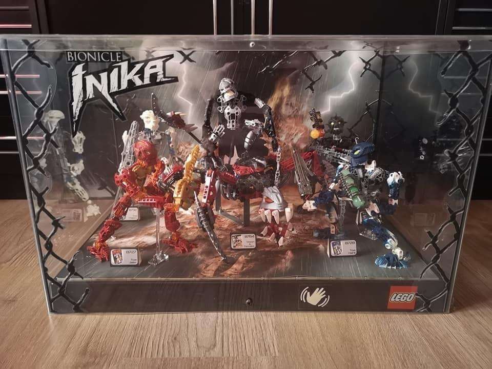
On top of this, I was told the following regarding both the larger display and the Jaller tube:
“The cable was routed along the arm to the back of the Toa. In the case of the small display, the cables were routed underneath the background paper. For the large display, the cables were routed through the Toa’s leg and under the base.”
While I’m unable to spot the cables in the image due to Instagram’s horrible compression methods (which is probably a good sign?), I at least have a good enough of an idea to figure out how to set up the cables for myself; the specifics of which I will figure out once I reach that step.
But first, I need a drill, and a very, very tiny drill bit.
A slight aside
Further regarding the display case shown above, it also provides a good example of what I’m wanting my final product to look like. Notably, I’ll be reusing the paper background and the small set information displays at the base of each Toa (and Vezon).
I plan to have the chain-link fence around the edges of the display by using armature wire, as previously mentioned in another blog post, and I plan to have a strip of paper running around the bottom. In the case of this display, this strip only has the Lego logo and a hand motion icon, but I have some ideas to make mine stick out a lot more.
I also particularly like the addition of the Inika logo on the top left, so maybe I’ll consider adding it on to my display. I’ll see how I’m feeling.
Checking up on a friend
I still have some time before I’m able to use the 3D printer, so I decided to check in on the XPS boards I had glued together a couple of weeks ago, because I just realized that I hadn’t done that.

They seem to have set well enough. They feel sturdy, but I wouldn’t be comfortable with applying a ton of force to them. The seam in the middle is bothering me quite a bit though, but I can figure out how to seal it up.
I went back to check North of the Border for some references, because I remember that he has a certain way of creating mud for his displays, and I planned to use whatever mixture he uses to fill in this seam.
Luckily for me, he just recently created a creative display featuring the popular Moo Deng (my beloved) and another pygmy hippo battling it out on an outdoor terrain.
While creating the base for Moo Deng, instead of using his typical combination of Mod Podge and some other items, he just used hole filler to create the mud. It’s so simple, it’s genius. So I now will buy myself some hole filler to seal the gap between my boards (and also to just have on hand).
Also, while I was scrolling through the video to see the mud process, I spotted Adam using the exact kind of drill I was thinking of using for the Inika swords. I suppose I had just forgotten I got that from him. I checked the description to see if he linked the exact drill he used, but no luck. I assume it doesn’t really matter which one I use though.
Fun fact! – Moo Deng’s name
Moo Deng is a pygmy hippo in Thailand, and as such her name is of Thai origin, with “deng” meaning “(to) bounce or spring”, and “moo” just meaning pork. So Moo Deng quite literally means “bouncy pork”!
Looking Out for the Little Guy
At long last I have the 3D printer available. I immediately put my sliced LED block model to print. Thankfully because it’s so small, it doesn’t take very long at all, even at the highest quality. This will be crucial for making the most of my time.
After a short time, I got this result:


Not bad for a first draft, but it definitely can be improved upon. The studs on my block are a little bit taller than the original, and seem to be just barely thinner in diameter. The LED slot is also too thin to fit an LED in without some damage. As for how it fits in the sword…


As they say: “Like a glove”. This surprised even me, as I fully expected to have more than a few measurements off by just enough to make a difference, but even the clips I designed are doing very well at their job.
There’s even enough extra room for a circuit board between the block and battery cover!
It isn’t perfect however. Like I said, I’ll need to readjust the tube where the LED will slot in, because even putting some force on the LED doesn’t make it slot in very well, and it also expands the plastic, meaning the block won’t fit in the sword as is.
I’m also thinking about making the battery compartment on the block hollow. Right now I just have it filled in completely solid, but hollowing it out will both reduce the print time even further, and also allow me to fit the cables in.
I applied these adjustments to the model in Blender to get this:

For the sake of documenting my changes, I hollowed out the battery casing but left a divider so cables would not touch, added a slight curve to the inside of the LED tube by using an elongated sphere to hopefully fit the LED better, and I also added a slight bevel to some edges for decoration and for (hopefully) an easier time putting the LED in the block.
These changes only removed a minute of printing time (down from 11), which is less than I hoped, but it’ll probably make a bigger difference with higher qualities.
But, after a few micro adjustments, and a little bit of a printer hiccup, I came out with this:

There’s a tiny bit of wiggle room for the LED, but it’s not noticeable enough to where I can confidently make another adjustment to the sizing, so this is fine enough.
But with that, we can now work on a functioning prototype block.
A Conundrum
I originally thought of using a cut to size perfboard to solder the LED and cables on to, but unfortunately, I discovered that perfboards are about twice as thick as the original circuit board in the sword.
It’s not really possible to cut them in half, or sand them that much, and I can’t afford to change the dimensions on my LED block to accommodate them, so I will have to reconsider my approach.
I tried to find a 1mm thick board online, but they are nearly impossible to obtain. It’s not going to be viable to have a company custom cut them, due to costs and time restrictions.
My next idea was to use connectors of some kind. The thought is that I would plug the LED “legs” into one side, and then have the power wires on the other, with the connector sat in the hollowed area of the block (which would require a redesign). Ideally, this would make it so the LED is secure and also so that it doesn’t have a chance of crossing wires and shorting out, while also making it more replaceable than if I were to solder the LED legs and wire together directly.
I dug around some of the electronic parts bins around the DKC for some ideas. Nothing really clicked for me until I found this beautiful cable:

I’m not entirely sure what it was, but something about this cable spoke to me. I had my doubts that it would just work or that it would hold the LED properly, but sure enough…

It works beautifully. I don’t think I’ve been so glad to be proven wrong.
Following off this success, I had a “eureka” moment while fiddling with the LED block. I removed the divider meant to keep the cables separate, and also created holes so that the legs could stick straight down without curving around anything, which led to this:

I think this is the way to go. It has everything I want, while also having the benefit of not needing to deal with solder. The only issue with this set up currently is that the cable is too large to fit in the sword.

Either of these two types of connectors would be my ideal option, since they only have two pin slots and are a lot smaller, meaning I can fit them in the swords much easier.
I’ll take a look online and see what I can find in terms of these.
Another Distraction
While brainstorming some ideas on how I could get this LED to fit, I ended up playing around with the Arduino coding and made a script to flash the LED in the same exact way as the original circuit boards.
I haven’t mentioned this up to this point, partially because I couldn’t be bothered to record it, but the Inika swords have a specific way of flashing for the extra cool factor, rather than just turning on or turning off.
Below is a video of Hahli’s sword performing this flashing (left), and my custom Arduino program controlling Matoro’s sword (right):
My camera’s framerate was a little low for this, but I can confirm that the lights flash in almost the exact same frequency.
I think this could be a fun addition to add to the final display. The normal state of the lights would be on or off, but I could have an additional, physical, button to cause this flashing. To see all six of the Toa with their swords flashing like this has always been somewhat of a dream of mine anyway.
Adding this as a separate function will require me to learn how to use inputs on the Arduino, but I am very confident it will be of no issue.
A Final Quick Update
The paints and tools I needed arrived on Friday, and despite having enough progress for this week to be satisfied, I decided to at least try on the new paints.
I applied some layers of grey paint on various parts of my test block of XPS foam, making sure that I would be able to see where the paint looked best. I put a layer on the Mod Podge primer, the straight black oil paint primer, and on the foam directly itself.
The oil paint I had applied earlier finally seemed to be dry, but hopefully this new acrylic paint will be fully dry after the weekend so I won’t need to wait weeks before being able to use the foam.
As for my other plans next week… I imagine it will take some time for the cable connectors I pick out to arrive, so in the mean time I’ll start planning how to attach the Toa to the foam board, and how I will hide all of the wiring on the display. I’d like to also start taking a look at how I’ll encase the display, and finally tackle the issue of the Plexiglass problem.
Should I become overwhelmed with that, my backup plan is to start planning out a design for all of the cosmetics I plan to print onto paper, and do research into the paper I’ll need. From my previous findings, this is going to be by far the most expensive part of the project just due to the sheer cost to size ratio of paper.
In the mean time, I’ll take a well earned rest.